 |
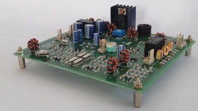
| KW4KD CW TRANSMITTER |
I got on 40 meter SSB over the weekend and spoke to Jim KW4KD. He was on a modern commercial rig, but then he told me he had some homebrew gear on his shelf… Wow, it is magnificent. A complete CW station (with homebrew keyer) AND an SSB rig. I immediately launched a campaign to get Jim to fire that gear up and to provide opportunities for more HB2HB contacts. Here is his description of the equipment:
Hi Bill,
It was a blast to get to chat with you too.
Just listening to the audio on this end, I can tell you’ve put a lot of time and effort into getting what you have there up and running.
Never once touched the dial on this end. So your radio gets a A+ for stability too.
Read your Bio on QRZ and sounds like you’ve been a few places, and seen a few things, and that unto itself would make a great contact . But for me, the fact that you are out there building, and I ‘m getting to hear the fruits of your efforts, is ham radio at its best.
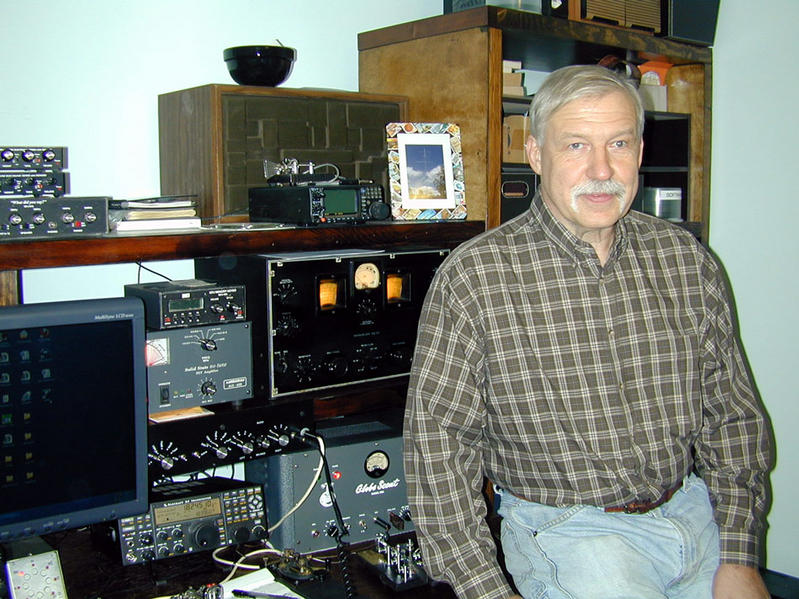
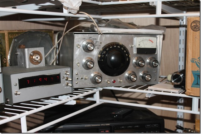
Attached are pictures of the gear that made up my station back in the 70’s.
FWIW: At that time my call was WB4YQC.
(But for the record, these shots were taken today.)
In those days I had two setups (Both on 40 mtrs).
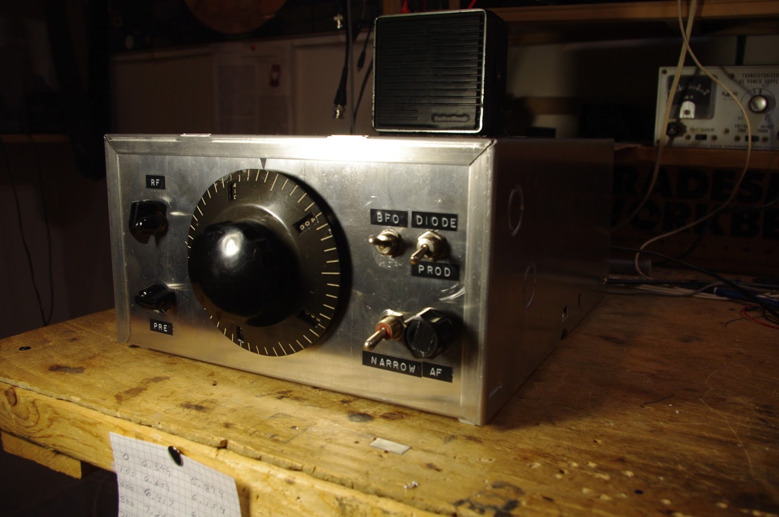
A CW station, using separate Xmtr & Rcvr, And a SSB xcvr.
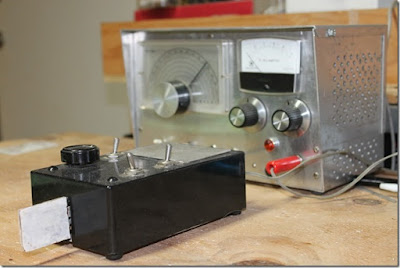
By themselves the CW xmtr ran 8 to 10 watts, and the SSB unit probably hit 5 Watts peak (on a good day).
Like you, I had a separate linear. But in my case I used a pair of 6DQ5’s (TV Sweep tubes) that would run about 180 watts input, (Nothing Solid State, that I could afford, could make that kind of power back in then). The linear is still here, but stashed away in a closet somewhere, so not shown in today’s set of pictures.
As an Add-On for the SSB unit, I built a Frequency Counter, and used it as a digital dial.
The counter is unique in that it supports two inputs (one for the VFO, and the other for the Xtal BFO). In the 2 input mode, the counter is an UP/Down counter.
The Xcvr’s BFO runs at 9Mhz, while the VFO runs at ~2Mhz. So the counter counts up on one pass, and then down on the 2nd. At the end of the 2nd pass, it updates the Display with the final tally. (i.e, the effective TX/RX freq)
The cases for the Xmtr & Xcvr were designed by me, but were built by a friend who had access to a metal brake. Internally none of the units are especially pretty, as the were always works in progress.
I’ll have to dust off the linear. Its been at least 40 yrs since its seen AC.. Not sure what kind of shape the electrolytics are in.
Probably need to apply power slowly. I’ll see if I can round up an Autotransformer.
As far as posting on your blog, if you think it will encourage others, I’d be flattered if you did;
However, before anybody asks, (assuming that they might) there’re no schematics. Everything was built from sketches made on envelopes and napkins, which have long since disappeared. And even if they did exist, not sure today that you’d be able to find some of the ICs & transistors that the units use.
Again, it was my pleasure to catch you on the band today, & look forward to getting to hear you again.
73 Jim (KW4KD)
 |
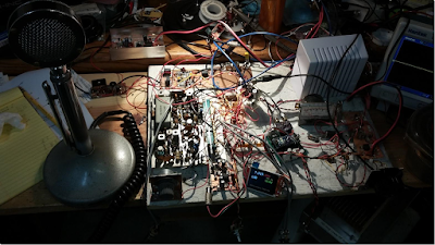
| KW4KD CW TRANSMITTER WITH HB KEYER |
 |
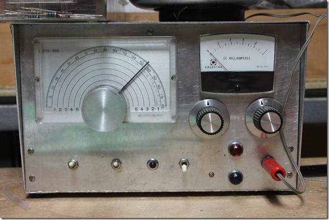
| 40 Meter CW receiver on Left |
 |
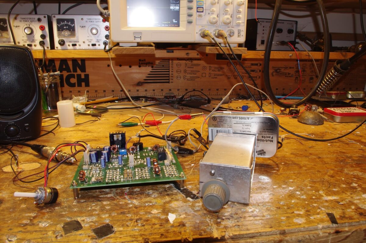
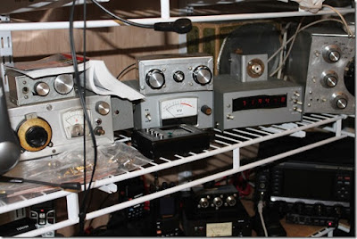
| 40 meter SSB transceiver with freq counter |