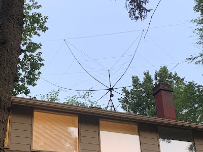
N2CQR Hex Beam Aimed at Europe
SolderSmoke #239 is available for download:
http://soldersmoke.com/soldersmoke239.mp3
TRAVELOGUE:
James Webb Space Telescope. Mars returning to opposition in early December.
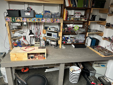
BILL’S BENCH
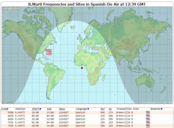
Hex Beam K4KIO – on roof – TV Rotor – 20-17-12 Lots of fun. Working Japan regularly, Australia, South Africa on long path 17,000 miles. 52 countries SSB since July 11.
VFOs and Temp stabilization. Dean KK4DAS found my ceramic resonator VFO for DC receiver drifty. He was right. So I built a real LC Colpitts VFO. Got me into temp stabilization. A new hobby! An obsession. HT-37 and Ht-32 parts. Ovens? WU2D’s second VFO video. Understanding thermal drift and how to address it. Split stator caps. Cut and try.
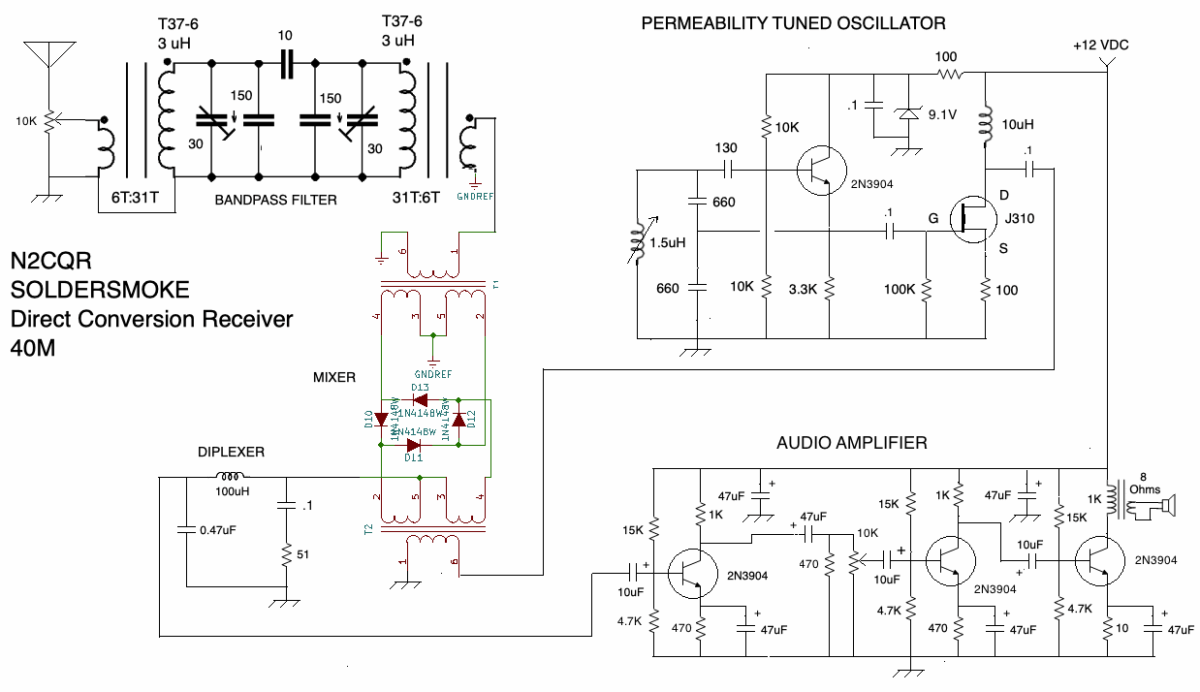
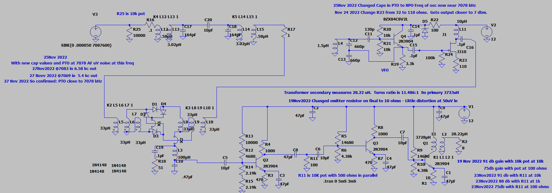
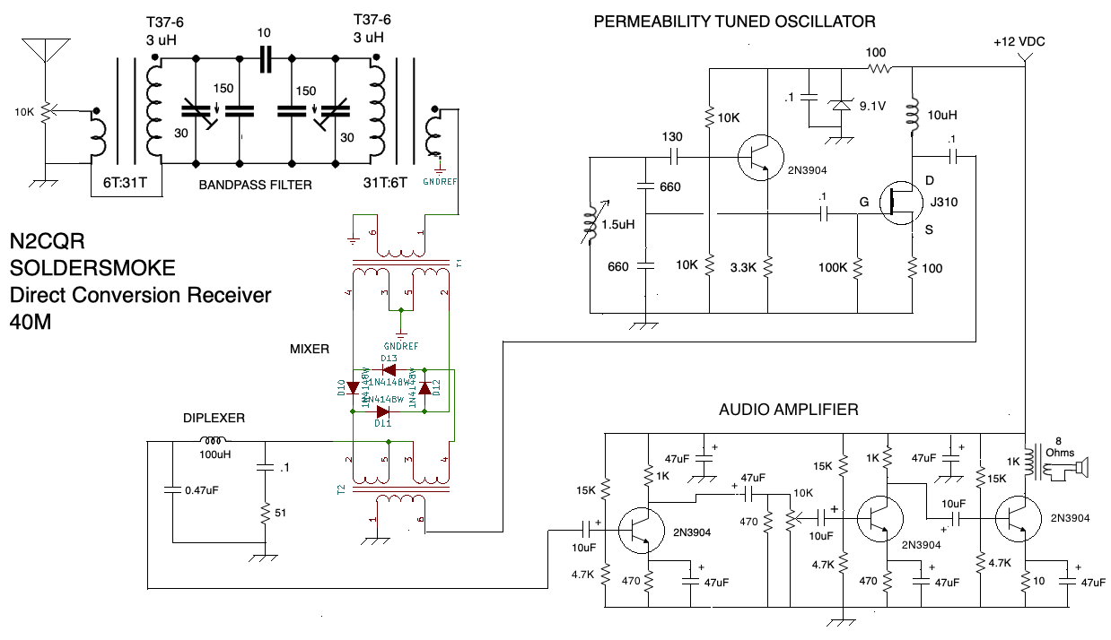
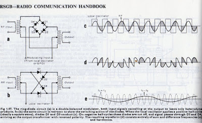
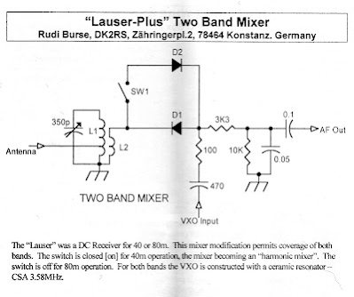
Built a Polyakov DC Receiver. https://soldersmoke.blogspot.com/2010/03/polyakov-plus-dual-band-receiver-with.html Lauser Plus. Lauser = Imp or Young Rascal! DK2RS. He used a ceramic Resonator VXO at 3.58 MHz. Mine works great on 40 with VFO running 3.5 — 3.65 MHz. See schematic below.
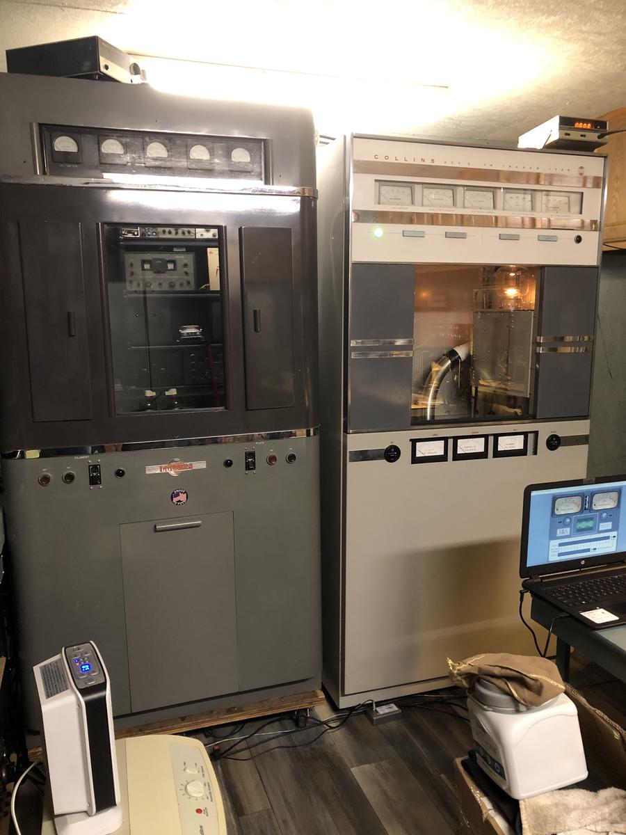
On 40 AM with DX-100 and MMMRX. DX-100 died. 12BY7 VFO buffer went bad. How common is failure in this tube type? Nice QSO with Tim WA1HLR about the DX-100.
Got my Dominican license: HI7/N2CQR! SSSS on the way. Thanks to Radio Club Dominicano and INDOTEL.
Getting more active in the Vienna Wireless Society.
BOOK REVIEW:
“The History of the Universe in 21 Stars” by Giles Sparrow. Written during the pandemic. Published by Welbeck, in London. https://www.amazon.com/History-Universe-21-Stars-imposters/dp/1787394654 Also: From “Atoms to Amperes” by F.A. Wilson available for download. See blog.
SHAMELESS COMMERCE DIVISION:
Todd K7TFC getting ready to launch “Mostly DIY RF.” I used his TIA boards in my 1712 rig. He will have boards like this and much more. Stay tuned.
I need more viewers on YouTube. They want 4,000 hours IN A CALENDAR YEAR! Please watch!
FARHAN’S NEW “DAYLIGHT AGAIN” RIG. Analog. VFO. Comments, observations. We need to get him on the podcast. Maybe two shows: SDR and HDR.
PETE’S BENCH
Time very limited. But still sharing lots of tribal wisdom.
Wireless set with tubes!
Tool recommendation – Air compressor
MAILBAG:
Farhan VU2ESE – Speaking of big antennas “Whenever I look at the huge construction cranes in Hyderabad, I always think how one could make 160m, 4 element yagi using it as a boom..”
Todd K7TFC in Spain, spotting Log Periodics in Madrid.
Andreas DL1AJG: Can Biologists fix Radios?
Janis AB2RA Wireless Girl. Expert on Hammarlunds. And was my first contact with the Tuna Tin 2. She too was HB!
Peter Parker VK3YE on Owen Duffy VK1OD
Lex PH2LB on homebrew radio
Would this really be homebrew? Mail from H-A-D article on FM receiver
F4IET a DSB rig from France
Ciprian got his ticket YO6DXE
Josh G3MOT sent us a good video about the Vanguard satellite and IGY.
Dave Wilcox K8WPE bought Chuck Penson’s Heathkit book.
Rogier — So many great articles and links from PA1ZZ
Bill AH6FC Aloha. Retiring. Wants to build. Mahalo!
Grayson KJ7UM Working on an Si5351. Gasp.
Mike KE0TPE viewing YouTube while monitoring 6 meters. He will have a lot of time to watch!
Chris KD4PBJ spotted Don KM4UDX from VWS FB
Mark WB8YMV building a superhet. Having trouble with 455 kc IF can filter.
Walter KA4KXX Great comment on the Daylight Again rig.
Ramakrishnan Now VU2JXN was VU3RDD. Found lost Kindle with SolderSmoke book on it. Building SDR rig from junk box. Trouble with the LM386.
Pete, Farhan and Tony: Shelves of Shame
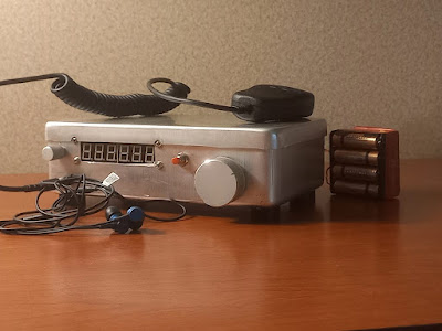
Daylight Again by Farhan
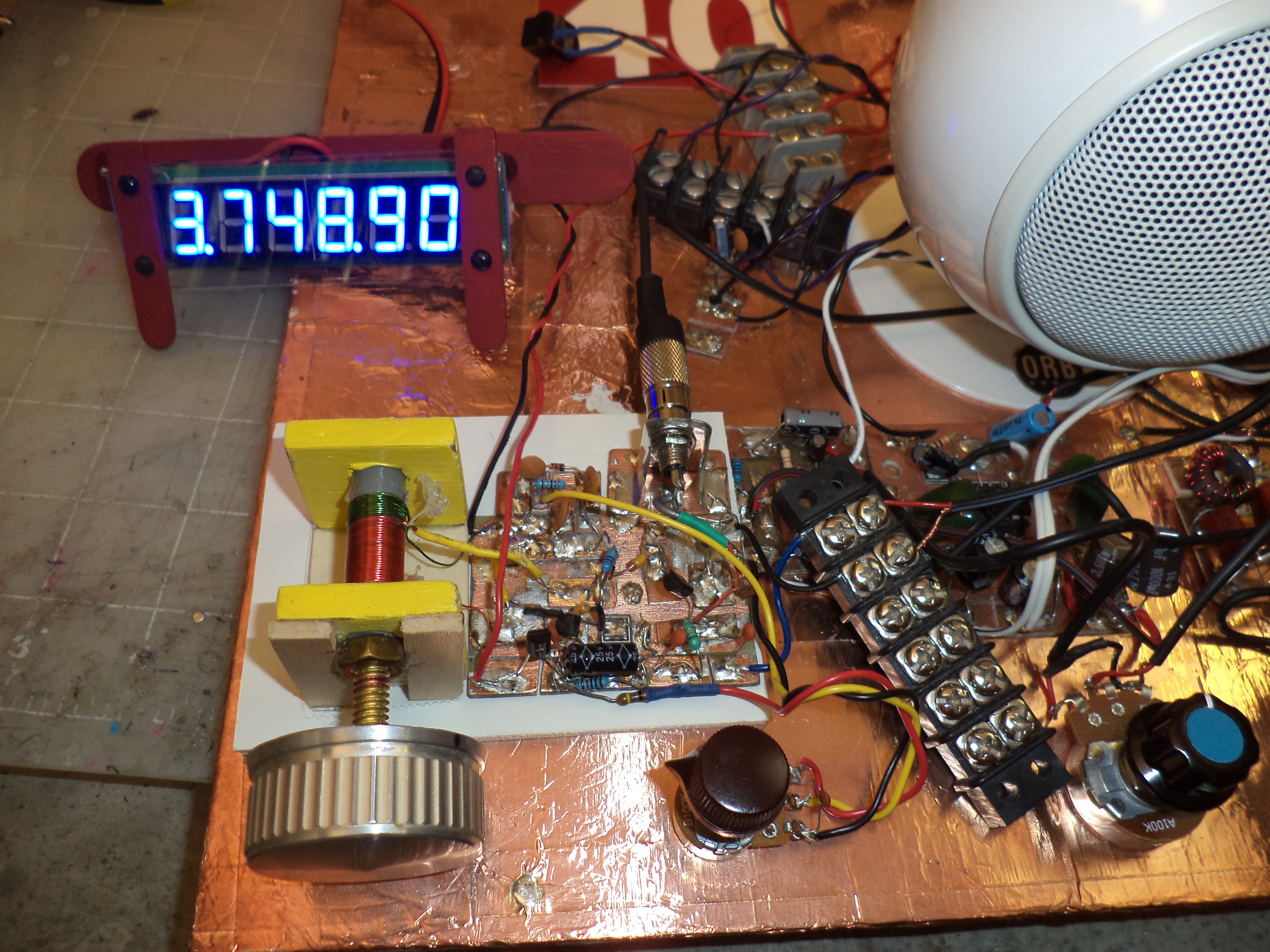
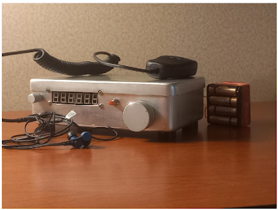
The Polyakov receiver I built yesterday (from SPRAT 110, 2002!)

.jpeg)
.jpeg)
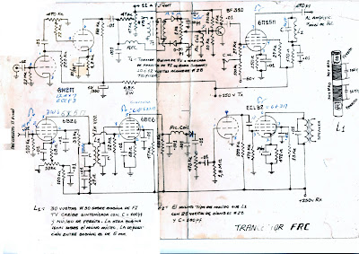
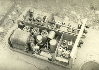
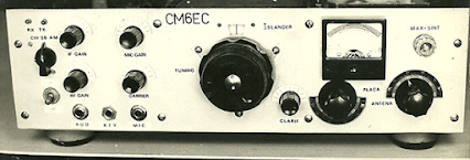
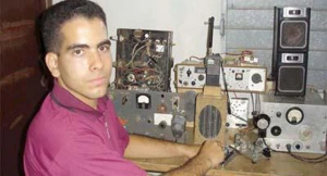


(co6ec) Jose de Jesus Enriquez Campos
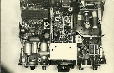
The first Image was the prototype presented at the Ganuza meeting, the rest of the photos were the ones we built with the improvements, and the photos and plans were sent to many colleagues, the colleagues who went to that meeting will remember, well, they still have to there are many left, because that was almost 30 years ago,
greetings CO6EC
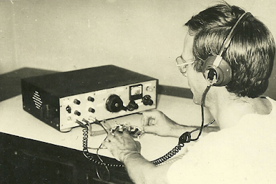
(co8zz) Raul Verdecie
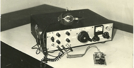
Magnificent photographs!!!… They seem to have been taken today with some digital “super camera”!!!
Really, from what I can see now, the CO6EC Islander was the perfect example… mine (my first radio and built by me) was also made like this, with the plates that the FRC sold and it was good, but very ugly …HI… The AGC worked wonderfully as it came, I don’t know if Jose’s improvements were later! With it I made my first hundred or so entities only in 40 meters / CW (between 7,100 and 7,150) when it was CL8ZZ. I gave it away so that someone would have their license and now I regret not having kept it… I would have liked to show it now to those who regret not having a radio!!!
(co8zz) Raul Verdecie
Ah, I can never forget those headphones!!!… my external hearing aids (read ears) are much smaller today thanks to them, they exerted tons of force on the operators’ skulls!!!
(cm6vml) Vidal
Very good article, I hope that one day, with a good teacher, I can build my own team, congratulations Jose, regards Vidal.
(co7wt) Pavel Milanes (CO7WT)
Sure…
My first radio and with which I got my CL7WT license back in the 90’s an ISLANDER, like that in capital letters.
I remember that the CL only had a small 40m segment (like now) and that it was full of broadcasts as soon as the afternoon fell, it was an odyssey to speak on the radio… you had to find a “little hole” between the Broadcastings where it wouldn’t bother you ” a lot” to be able to talk.
I remember that the old CO7OC (he is no longer a radio amateur) and CL7HU (now AC7HU) helped me build it with a board I bought at the radio club. I took almost all the valves from the deceased KRIM 218, then I found a store in Camagüey that sold idle things from the workshops…
Turns out they had such a large inventory of “idle” tubes that they couldn’t put it on the counter…they let me through to the warehouse…huge…stack of tubes, if I remember correctly I ended up with Chinese or Japanese tubes that they were more sensitive in the receiver… the driver went from a 6P14P to a more robust 6P9, by the end that was a humble 6P44 it became two 6P7s that were a Russian version of the RCA 607 if I remember correctly… in the end it had like 80W.
It goes without saying that when I said on the radio that there were valves in that place “they flew”….
The VFO was the one from the Jagüey, not the original from the Islander, I never knew about the AGC modifications.
I would like if someone has the plans with the modifications to send them to me, just for nostalgia…
My email pavelmc@gmail.com
(co2jc) Carlos Alberto Santamaría González
Brother, your article is very good, because of the nostalgia and also because it talks about what we radio amateurs like: tinkering. I didn’t have an Islander because what I started with in 2000 was a Polosa to which two colleagues helped me adapt it with VFO for 40 and 80 m. But I talked a lot with colleagues who did it with an Islander or a Jagüey and participated in the Rueda del Behique that I started in the 80 m. Others in the Hurricane Wheel that started a little later and were heard well. As you well say, the propagation at that time had nothing to do with what it is now, but it was very good to listen to the colleagues who came out with the equipment they had built. Thank you once again for your article. CO2JC