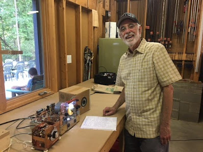
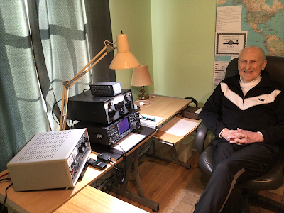
Hall of Fame member Steve WD4CFN in Tennessee fired up his 40 meter Mchigan Mighty Mite (above) and made contact with ND4K in Georgia. FB Steve. Congratulations OM!

SolderSmoke Daily News — Ham Radio Blog
Serving the worldwide community of radio-electronic homebrewers. Providing blog support to the SolderSmoke podcast: http://soldersmoke.com
Hall of Fame member Steve WD4CFN in Tennessee fired up his 40 meter Mchigan Mighty Mite (above) and made contact with ND4K in Georgia. FB Steve. Congratulations OM!
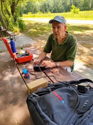
I have made 11 contacts using the SolderSmoke Direct Conversion receiver. Ten of the 11 were after June 3, 2025. This was in very casual operation, operating with less than 1 watt with a dipole antenna.
1. The first of course was back in February 2023 with W4AMV. On this one I was using a simple “10 Minute Transmitter” that I threw together thinking that I would use it to demonstrate the receiver to our high school students. “Wait a minute,” I thought. I called CQ and W4AMV answered. I was running about 100 mW. He too was using homebrew gear. https://soldersmoke.blogspot.com/2023/02/first-qso-with-high-school-receiver-100.html
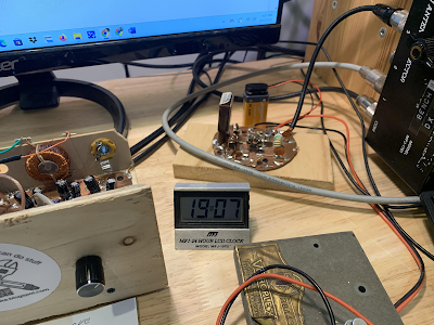
2, 3, 4. On June 4, 2025 I again fired up the 10 minute transmitter. My T/R scheme was VERY simple: I have an MFJ coax switch that I use to select the rigs that will connect to my various antennas. On the antenna switch I selected my 40 meter dipole. I ran two pieces of coax from two different positions on the MFJ switch. One I marked RX, the other TX. The transmitter and the receiver were working off 9 volt batteries. I quickly worked N2WJW. Gil in New Jersey. But I noticed that the 10 Minute rig was drifting. So I pulled out my trusty old Tuna Tin 2 transmitter and used it to heartlessly replace the 10 Minute Transmitter. Now with SEVERAL HUNDRED milliwatts, I worked W2XS, John in New York on June 5, 2025. Later that same day I worked N9FGC in Indiana.
5. My most amazing contact came on June 7, 2025. Here is my log entry: 40CW K1OA First 2 way contact with station also using a SolderSmoke DC Receiver!At around 0630 EDT on June 7, 2025 I heard K1OA calling CQ on 7030 kHz CW. This was exactly where I had a crystal. I called him, but he didn’t hear me. I sent him an e-mail. We tried again — he heard me calling him and I heard him responding by calling me, but I don’t think we succeeded in exchanging signal reports. It was close, but no cigar. I had to walk the dog. Scott and I agreed to meet on 7030 kHz at 0730 EDT. Arggh. There was a QSO there. I thought we might have to try to change frequency, but this would have been tough because both of us were crystal controlled on transmit. Fortunately, the contact on 7030 kHz wrapped up. Scott called me, I responded, and we were able to exchange signal reports. I was so excited that I almost forgot to hit the record button on my phone. But I caught the last minute or so.This was really something. This really goes to prove what Dean and I have been saying all along: this receiver is not a toy! It can be used for real ham radio contacts. And now we have had these receivers on both ends of a contact. For transmit, Scott was using a KA4KXX transmitter with about 3 watts output. I was on my Tuna Tin 2 at about half a watt output.
6, 7, 8. Later on June 7, 2025 I worked an old friend, Jim W1PID. Jim is a friend of Homebrew Hero Mike AA1TJ, and was involved in Mike’s effort to cross the Atlantic with a voice-powered rig. Jim also was one of my contacts with the ET-2 QRPppp rig. I also worked WZ2J Vin in NJ. I also worked John W2XS again.
9. June 11, 2025 (Really evening of 10 June 2025) Famous homebrewer, Anchorologist, Heatkit authority and fellow member of the QRP Hall of Fame Mike Bryce called me! 40CW 0034 WB8VGE Mike Bryce came back to my CQ! Mike wrote: Nothing like quartz locked frequency control!You know it sounded pretty damn good at 500mW. You were holding your own until QSB would take you out in a deep fade. But all in all, one hell of great QRP QSO.I was running my Ten Tec Scout that I had just put back together a couple of days ago. Got around to putting the case back on it tonight, and had it cooking in the back ground just listening to the stations come and go. I had worked a few POTA stations near by and found a quite spot. I was working on a project when I heard your CQ through the din of the 40M band. Glad I took a break and worked your QRPp signalbest 73 QRP # 4816 You get a QSL for that QSO!
Here’s my post about Mike, WB8VGE: https://soldersmoke.blogspot.com/2018/09/wb8vge-on-qso-today-qrp-hb-boatanchors.html
10. Around June 11, 2025 I worked W4MY in a contest.
11. On June 12, 2925 I worked some DX with the rig. It was VA3ICC, Ian in Ontario.
At around 0630 EDT on June 7, 2025 I heard K1OA calling CQ on 7030 kHz CW. This was exactly where I had a crystal. I called him, but he didn’t hear me. I sent him an e-mail. We tried again — he heard me calling him and I heard him responding by calling me, but I don’t think we succeeded in exchanging signal reports. It was close, but no cigar.
I had to walk the dog. Scott and I agreed to meet on 7030 kHz at 0730 EDT. Arggh. There was a QSO there. I thought we might have to try to change frequency, but this would have been tough because both of us were crystal controlled on transmit. Fortunately, the contact on 7030 kHz wrapped up. Scott called me, I responded, and we were able to exchange signal reports. I was so excited that I almost forgot to hit the record button on my phone. But I caught the last minute or so. See above.
This was really something. This really goes to prove what Dean and I have been saying all along: this receiver is not a toy! It can be used for real ham radio contacts. And now we have had these receivers on both ends of a contact. For transmit, Scott was using a KA4KXX transmitter with about 3 watts output. I was on my Tuna Tin 2 at about half a watt output.
Thanks Scott! And thank you Walter!
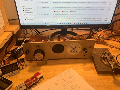
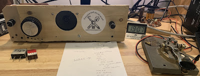
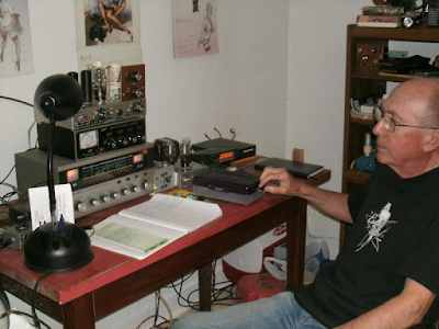
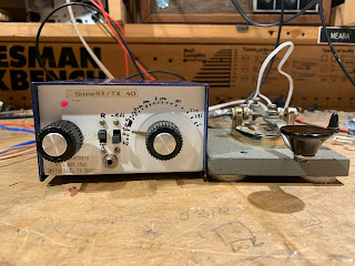
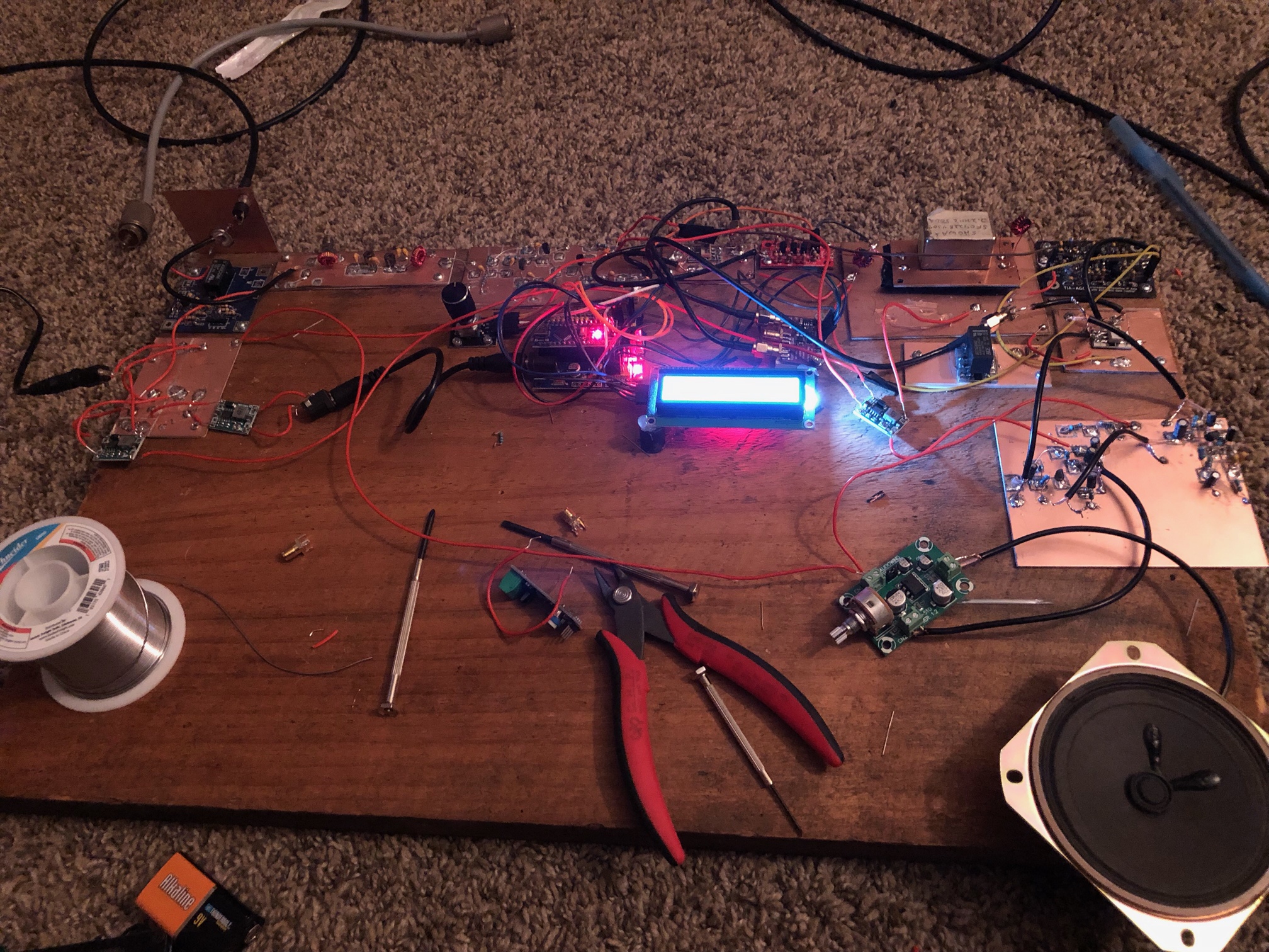
Inspired by K1OA and KA4KXX, I put the SolderSmoke DC receiver to work on the CW portion of 40 meters. At first I used a very (perhaps overly) simple “Ten Minute” transmitter. On June 4, 2025 I worked N2WJW in New Jersey. But the transmitter drifted as it got hot. So I switched to the more robust Tuna Tin 2 (TWO transistors!) and worked W2XS in NY and N9FGC in Indiana on June 5. With both transmitters I was “rock bound” — crystal controlled. Power out was always less than 200 milliwatts. Antenna was a low to the ground dipole. The receiver was powered by our beloved 9V battery. The transmitter had a second 9V battery. Some observations: First, even if you CAN hear other signals, the different tones allow your brain to seperate them out (this has long been known to CW operators, but might not be readily apparent to newcomers). So even if the DC receiver is broad in frequency response and even though it IS also receiving the other side of zero beat, you can make CW contacts (unless, of course, another station is on a frequency that produces exactly the same tone as the one you are trying to work), even at very low power . Second, you don’t always really have to be right on the other station’s frequency. Here’s why: If he is looking he can see you in his waterfall! So that SDR waterfall is now a friend to crystal-controlled HDR operators. Who would have thought? Above is a picture of the my station with the Ten Minute transmitter. See the notes I wrote on the QSO with N2WJW.
Check out this short video of Calvin’s receiver in action:
https://www.youtube.com/shorts/BbcBVmmKygw
Thanks Calvin!
Join the discussion – SolderSmoke Discord Server:
Documentation on Hackaday:
https://hackaday.io/project/
SolderSmoke YouTube channel:

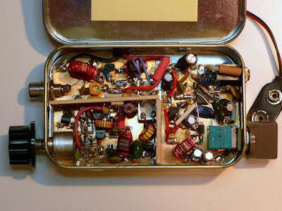
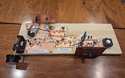
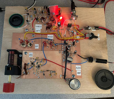
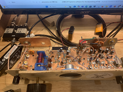
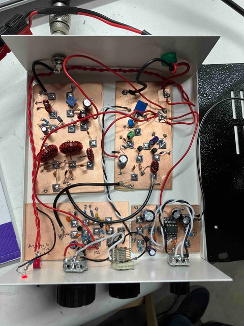
It is a thing of beauty. You can see all four stages in there. There is the Bandpass Filter in the upper left. Below that is the VFO. In the center you can see the SBL-1 mixer. Off to the right is the audio amplifier. FB Chuck!
Chuck KE5HPY writes:
Allow me to add an endorsement of the joy and practicality of the DC receiver. Whether XTO, VFO or DDS, ring diode mixer, or Polykov, the DC IF concept is a real winner. They really deliver wonderful audio and clarity that is very satisfying for homebrew builder.
We prepared this for use by the high school students who were building direct conversion receivers. Unfortunately none of them got to the point where they would use this little article, but given the fact that a number of people are now engaged in direct conversion receiver projects, I thought it would be a good idea to post this here. Also, much of this applies more generally to receiver problems.
My receiver doesn’t work right!
What should I do?
First, relax. You will be able to get it to work. The design is good, people around the world have built this receiver, and you will be able to get it to work. But homebrew radio is not plug-and-play radio. Sometimes a new receiver needs some tweaking, peaking, and coaxing.
Realize that the 40 meter band has its ups and downs. The downs usually come at mid-day. The sun’s position high in the sky causes a build up of the D layer of the ionosphere. This tends to absorb radio waves. So signals are often weak at mid-day. Signals will be much stronger in the morning, and in the evening.
Can you hear the “band noise” when you connect your antenna? This sounds like hiss or static. Some of this is the result of thunderstorms in Brazil. Some of it is from events far away in the cosmos. Some of it comes from the weed whacker down the block! But if you can hear this noise, that is a very good sign that your receiver is working. The signals you are looking for will be stronger than this band noise.
Where are you tuning? Your receiver tunes from about 6.8 MHz (with the screw all the way our) to about 7.8 MHz (screw all the way in). But we are only really interested in the ham frequency band between 7.0 MHz and 7.3 MHz. Try to tune your receiver near the middle of the tuning range (with the screw about half-way in). You should hear morse code from about 7.0 to 7.06 MHz. Then you should hear strong digital signals at 7.074 MHz. Tuning further up (screw going in) you should start to hear hams speaking to each other using Single Sideband. At first they will sound like Donald Duck.
Sometimes you will only hear one side of the conversation. That is normal. The other station may be either too far away from you, or too close to you. You may be outside his or her skip zone.
One very obvious thing to check: How is your battery? Is it drained, or is it still at about 9 volts? You may need to change it.
How is your antenna? It doesn’t have to be fancy or elaborate. 33 feet of wire will do. But it does need to be up in the air a bit. And you need to have the 33 foot counterpoise wire connected to the ground (on the PC board). With many pieces of consumer electronics antennas are kind of optional – the devices will often work without them. Not so with ham gear. Antennas are important. If you are not receiving signals, it may be because of your antenna.

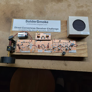
The folks over at Ham Radio Workbench have graciously accepted the challenge issued in our last podcast: that they scratch-build homebrew the 40 meter Direct Conversion receiver that Dean KK4DAS and I designed for local high school students. We want to help our brothers over at HRWB. For example, we may be able to supply a few of the 3D printed PTO coil forms. Here is some background information on the project.
Design Decisions in the Direct Conversion Receiver
Why did we do it this way?
In thinking about how to design this receiver, we had to make early design decisions on almost every stage. Here are some of our key considerations.
VARIABLE FREQUENCY OSCILLATOR:
Normally we might have used a variable capacitor to change the frequency of this oscillator. But variable capacitors are now expensive and hard-to-source. Our friend Farhan in Hyderabad used a simple variable inductor for this purpose in his “Daylight Again” transceiver. The coil form for this part could be 3D printed. A metallic screw would vary the inductance as it is screwed in and out of the coil.
We also decided to use the same simple Colpitts oscillator circuit used by Farhan in his own high school direct conversion receiver. This circuit is unusual in that the feedback capacitors are also the frequency determining elements (along with the variable inductor). This simplified the circuit and reduced the parts count, and proved to be remarkably stable.
For the VFO buffer we used the simple JFET buffer from Farhan’s Daylight Again design.
Based on suggestions from other radio amateurs, we developed a simple frequency readout based on the position of the end of the tuning screw (how far in or out?).
We selected the 40 Meter band for this receiver because we thought it would be easier to get the VFO stable on this frequency, and because Farhan had built his receiver for 40 meters.
MIXER:
At first we hoped to use a simple singly-balanced mixer using two diodes and a single trifilar transformer. But we found unacceptably high levels of AM breakthrough (mostly from Radio Marti on 7335 kHz) when using this circuit. So we switched to a diode ring. This required two more diodes and an additional trifilar transformer. We believed the students would have great difficulty building and installing two trifilar transformers so early in their building experience. So we used transformers that had been wound in Hyderabad by a women’s collective employed by Farhan, and developed a scheme for fool-proof installation of these transformers.
We also found that the mixer needed a diplexer at its output – this would provide a 50 ohm termination at all frequencies and would result in much cleaner action by the mixer and greatly reduced AM breakthrough from Radio Marti. We used the same circuit used by Roy Lewellen W7EL in his Optimized Transceiver circuit.
BANDPASS FILTER:
This was the simplest board in the project but it required the students to wind two coils on toroidal cores. A simple dual-tuned circuit design would be sufficient. We used component values from the QRP Labs website. We showed them how to wind the coils, and made a video about the technique. Students used a simple Vector Network Analyzer (Nano VNA) to tune the filter.
AUDIO AMPLIFIER:
We had to make several design decisions here. First, we rejected the idea of using an IC amplifier like the ubiquitous LM-386. We wanted this to be a completely analog and discrete component experience. Then we rejected the idea of using a push-pull output circuit. While this would have eliminated the need for an audio output transformer, it would have resulted in a more complicated circuit. In the end we opted for three simple RC-coupled common-emitter amplifiers with an audio output transformer. There was no feedback in these circuits. We found there is a lot of gain (hFe) variation in the 2N3904 transistors that we used. Care needs to be exercised in making sure that transistors of moderate (but not too high) gain are used.
This AF amplifier chain probably presented a 1500 ohm impedance to the mixer (instead of the desired 50 ohms), but we think this problem may have largely been taken care of by the diplexer.
We found some very small (one square inch) speakers that could be easily used in this circuit.
ANTENNA:
While the students could use a wide variety of antennas, we recommended a simple ¼ wave antenna with a ¼ wave counterpoise. We thought that this antenna – of only 33 feet in length would provide good performance with low complexity, and would be well suited to the “upper floor bedrooms” from which many of the students would be listening. Also, this antenna would not require the use of coaxial cable or an impedance matching transformer. We made a video on how to build and use this antenna.
POWER SUPPLY:
We opted for the use of 9 volt batteries. This proved to be a safer and wiser choice that limited the kind of mayhem that could occur should a variable voltage supply be used.
Details on the receiver can be found here:
https://hackaday.io/project/190327-high-schoolers-build-a-radio-receiver
May 29, 2023

I finished my first super het receiver. It’s for the 40m band. It consists of: bandpass filter, tuned amp, diode ring mixer, wide band amp, crystal ladder filter, wide band amp, then SA602 + LM386 combo. I learned tons as i put all the components. First two amps are my design. The third amp is bga2866. The bandpass filter is what i posted a few days ago. I planned to make another one but with 2.5db insertion loss i thought it was good enough.

Walter KA4KXX spotted an error in the schematic of my 2014 “Off the Shelf” regen receiver: The source resistor on the MPF-102 should be 2200 ohms, not 2.7 ohms. See:
https://soldersmoke.blogspot.com/2014/09/schematic-for-off-shelf-regen.html
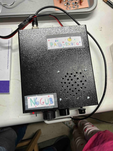
Geoff N6GWB and his eldest have produced a really wonderful receiver, and have joined the elite ranks of those who have built their own receivers. Congratulations to both! ( Be sure to watch the video below.)
Geoff writes:
Though I built it, my eldest has retained naming rights. Behold the Rad Radio Receiver, an Soldersmoke inspired build. It’s a 40m DC reciever. I had planned on making this a truly 50-50 N6QW N2CQR build, but I needed to get it done for a show and tell this Wednesday. I have N6QW dual JFET RF amp and mixer modules. I have the N2CQR ceramic ocillator circuit from the 2017 DC receiver project. I had planned on including the all analog audio amp from the more recent N2CQR DC project, but alas, time got the best of me. I was hoping to make the whole thing all-analog. (I thought the all analog would get me more “hard work” kudos at the show and tell.) I ended up including a LM386 audio amp making this a bit of a cyborg.
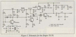
Click on schematics for a better view
I picked this transceiver up at Winterfest for one dollar. 40 meters. Superhet receiver with 455 kc ceramic filter and 2 NE602s. Crystal controlled one watt transmitter on 7039.5 kc. I emailed Jeff KA2BKG and asked him to slide up a bit to my freq. I am glad he did. Thanks Jeff.
Bill,
I am sending video and pictures of my 40m superhet that I built. I have it on the floor in an extra room in the house. The antenna is a stock vhf dipole that came with my rtl sdr which I use as a spectrum analyzer. In one of the clips I am receiving RW7K. I have been working on the station for the past year with help from Loren Moline, WA7SKT through texts when I have a problem. The LO / VFO is from Nick Woods Videos.
Next, I will build an outdoor antenna and the transmitter section. I first started homebrewing at the beginning of the pandemic, but this is by far my largest accomplishment. I would like to thank you and Pete for the soldersmoke videos which have been a great inspiration.
I will send more updates when the transmitter section is finish along with a much longer description of the projects
Thank you
Justin Elliott
AC8LZ
Bill, Pete, and Dean