
Author: William Meara
Video: Rob Sherwood NC0B on Transceiver (and Especially Transmitter) Performance
Rob Sherwood NC0B is one of the real authorities on receiver performance. Many of us have relied on his ratings of commercial receivers for many years. His recent presentation to the Madison DX Club has a lot of really interesting information. There is also, I think, some stuff that homebrewers will find distressing.
Just some things that I noticed:
— Rob mentioned a move back to 9 MHz IF filters and a move away from dual-conversion rigs with a high IF. He also mentioned the combination of a 9 MHz IF and a 5 MHz VFO as a way of easily getting on both 75 and 20 meters.
— Rob discussed phase noise from synthesizers, a topic we discussed at length (some would say ad nauseum!) a year or so ago.
— Rob really praised the “Pure Signal” system of one of the SDR manufacturers. He showed the completely rectangular waterfall display of a Pure Signal transmitter. I’m afraid that simple crystal rigs might never live up to this standard. An embrace of this high standard could discourage the construction of simpler, HDR rigs. We should not let the perfect be the enemy of the good!
— We often hear SSB ops complaining that some other SSB op is “splattering all over the band.” It often turns out that what is really happening is that a clean SSB signal is just overloading the receiver of an operator who does not know how to turn off his pre-amp or turn on an attenuator. Rob shows us how to really know if the problem is in fact at the other end: He looks at key clicks from two different CW signals on 160 meters. Both are at roughly the same level in his receiver But one is clicking all over the place while the other is not. With this kind of comparative info, we can be sure that the problem is the transmitting station’s fault.
— In discussing when to turn on the pre-amp (or the attenuator) Rob revives the old practice of just listening to the band noise. If you can hear the band noise when you switch from dummy load to receive antenna, you have enough RF gain. Adding more will only make things worse.
— There was an interesting question about how to evaluate the performance of receivers when there are many signals inside the receiver’s passband. This is the case with FT-8. Rob said this situation needs more research.
I don’t mean to be critical here — Rob is the guy who evaluated commercial rigs. And he is a contester. So his presentation is, of necessity, going to have a very “appliance operator” orientation. There seems to be an assumption that the only “rigs” that modern hams can use are commercial products. At one point Rob admits that most hams just can’t repair these rigs. There is much for homebrewers to learn from experts like Rob, but presentations like this also remind us of what a tiny minority we really are, and how most hams have moved completely away from the old ham tradition of building our own rigs.
Thanks to Rob Sherwood and the Madison DX Club. And thanks to EI7GL for alerting us to this important presentation.
Video: Introduction to the TinySA Spectrum Analyzer
The TinySA has some very cool capabilities, and this short intro video provides a good sense of what it can do.
I am learning how to use the TinySA so that I can check the output of my Mythbuster transceiver (I now have the first portion of the transmitter working.) I tried to use the TinySA to check the carrier and opposite sideband suppression on my new Mythbuster transceiver, but I think the max Resolution Bandwidth (3 kHz) is too high for me to do this. Please let me know if I am missing something. That would have been a very useful capability.
The rest of the videos are here:
It also functions as a signal generator that also provides AM and FM modulated signals. You can also have a waterfall on the spectrum display. Very nice.
I have not yet figured out how to listen to the signals. This is one of Erik’s videos — it looks like you have to solder in a connection for audio out.
Thank you Erik Kaashoek.
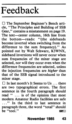
50 Shades of Homebrew? PH2LB’s Shack and NanoVNA Adapters
That would have been a very different movie. And I don’t think the box office results would have been favorable. That’s PH2LB’s “pleasure room” (shack). He has a good blog focused on homebrew:
Lex has also made some very cool adapters for measuring filters with the NanoVNA:
Thanks Lex.
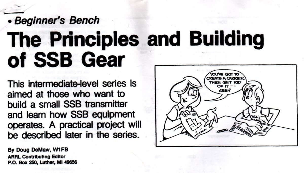
QST Recognized Error on Sideband Inversion, But Continued to Make the Same Mistake
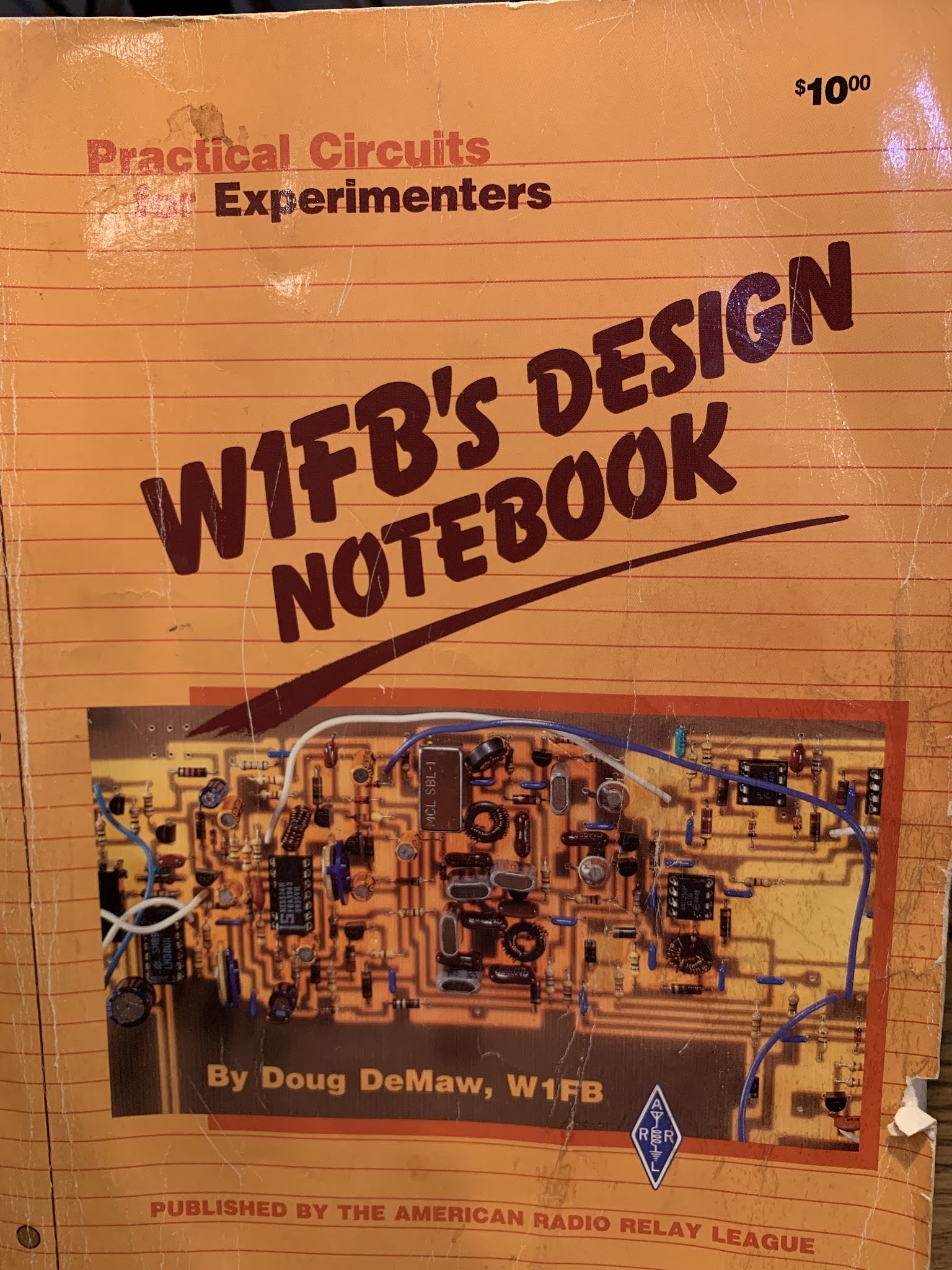
I don’t really know if this is good news or bad news. It’s good that in November 1985 they recognized the error, but then they allowed the same error to be repeated by the same author in the 1989 article “A Four-Stage 75-Meter SSB Superhet,” and again in 1990 in W1FB’s Design Notebook. It also made it into the 2002 ARRL Handbook.
Thanks to Chuck WB9KZY for alerting us to this Feedback piece.
QST Repeatedly Got Sideband Inversion Wrong
It kind of pains me to do this. These articles are from a long time ago, and the author is an esteemed Silent Key, but the myth about the origins of the USB/LSB convention is still out there, and as a homebrewer of SSB gear I feel obligated to point out these examples of the error that that myth is based on.
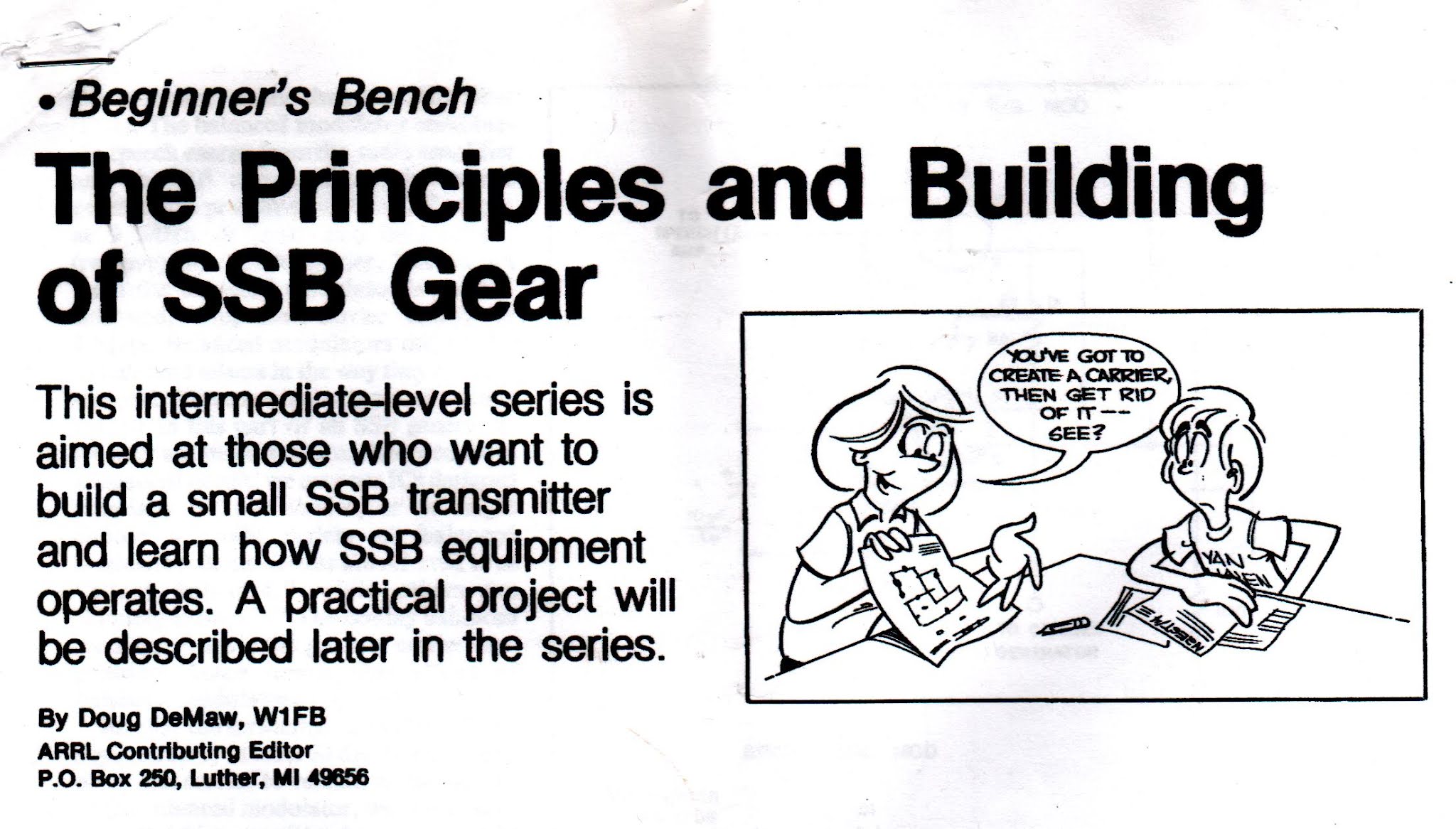
Last Friday, Pete WB9FLW and I were talking about homebrewing SSB rigs. I recommended a series of QST articles by Doug DeMaw. “Beginner’s Bench: The Principles and Building of SSB Gear” started in QST in September 1985. There were at least five parts — it continued until January 1986. (Links to the series appear below.) I hadn’t looked at these articles in years, but when I did, a big mistake jumped right out at me: In the first installment, on page 19, Doug makes the same mistake that he made in his Design Notebook:
“Now comes the conversion section of our SSB generator. We must move (heterodyne) the 9-MHz SSB signal to 3.75-4.0 MHz. Our balanced mixer works just as it does in a receiver. That is, we inject the mixer with two frequencies (9 MHz and 5 MHz) to produce a sum or a difference output frequency (9 – 5 = 4 MHz, or 9 +5 = 14 MHz) If we are to generate 75 meter SSB energy, we must chose the difference frequency. We could build an 20-meter SSB transmitter by selecting the sum of the mixer frequencies. The RF amplifiers and filter (FL2) that follow would then have to be designed for 14-MHz operation. In fact, many early two-band homemade SSB transmitters were built for for 75 and 20 meters in order to use this convenient frequency arrangement. The use of upper sideband on 20 meters and lower sideband on 75 meters may be the result of this frequency arrangement (the sidebands become inverted when switching from the difference to the sum frequency.) ”
Those last two sentences are incorrect. They repeat the “Myth,” or the “Urban Legend” about the origins of the LSB/USB convention. Contrary to what many hams now believe, with 9 MHz filter and a 5.2 MHz BFO it takes more than just switching from sum frequency to difference frequency to invert one of the sidebands.
There are two conditions needed for sideband inversion to take place:
1) You have to be taking the difference product (DeMaw got that right)
2) The unmodulated (VFO or LO) signal must be larger than the modulated signal. (DeMaw and the ARRL obviously missed that part. Repeatedly.)
This is another way of stating the simple, accurate and useful Hallas Rule: Sideband inversion only occurs when you are subtracting the signal with modulation FROM the signal without modulation.
For DeMaw’s claim to be correct, one of the SSB signals going into the balanced mixer would have to invert, and the other would have to not invert. Let’s see if that happens: He has the sideband signal being generated at 9 MHz and the VFO running around 5 MHz.
9 – 5 = 4 But we are not subtracting the modulated signal FROM the unmodulated signal. SO NO INVERSION
9 + 5 = 14 We are not subtracting at all. SO NO INVERSION.
Doug’s convenient frequency scheme WOULD work if he’d just switch the frequencies of the filter and the VFO. With a sideband generator on 5.2 MHz and a VFO around 9 MHz you do get the happy 75 LSB, 20 USB arrangement without the need to switch the carrier oscillator/BFO frequency. That is what happened in the Swan 240, and that is what I have in my Mythbuster rig. I am listening to both 75 LSB and 20 USB without changing the carrier oscillator/BFO frequency. My filter/BFO/product detector is set up for USB. With this arrangement the 75 meter LSB signals DO invert, and the 20 meter USB meter signals do not, so both are able to make use of my USB BFO/product detector without shifting the BFO frequency.
This error shows up again in DeMaw’s the May 1989 QST article “A Four Stage 75-meter SSB Superhet” (reprinted in the ARRL’s QRP Classics book). Here he writes:
“Should you want to cover both the 75- and 20-meter bands you can build a 20-meter version of FL-1 and band switch the two filters. As with the 75 meter only version, an IF of 9.0 MHz (Y1) is required. With this arrangement the 20 meter band will tune backwards from the 75 meter band, but upper- and lower-sideband reception will occur, as required, without changing the BFO frequency (Y2). This two band scheme with a 5-MHz VFO is an old one!” NOTE: FL1 is the bandpass filter, not the IF filter.
Doug’s mistakes in this area may simply be due to the fact that he was more of a CW guy. And this is something that is quite easy to confuse: 9 and 5 will get you to 75 and 20, but you have to make sure the VFO is at 9 if you want to make use of sideband inversion and avoid having to shift the BFO/ carrier oscillator. I’ve made this mistake myself:
In October 1993 I wrote to DeMaw about his Four Stage 75 meter SSB Superhet. I think I was looking for details on how to put it on 20 meters. As I recall, Doug wrote back telling me to just pick 20 meter values for the input bandpass filter. Had I done so, I would have discovered that — for the reasons cited above — this just wouldn’t have worked on 20. His BFO and filter were set up to receive LSB signals. That’s fine for the incoming 75 meter LSB signals. But on 20 — contrary to DeMaw’s thinking — there would be NO sideband inversion. I’d be trying to listen to 20 meter USB signals with a receiver set up for 20 meter LSB.
Did anyone else notice these errors. Were there ever errata notices in QST on this?
This is a reminder that you should take all technical articles and schematics with a grain of salt. Many contain errors. We are all human, and this is a complicated subject with lots of details.
Possible Victory for Frank Jones and the FMLA? Could We Get the 5 Meter Band Back?
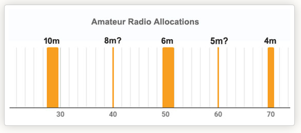
EI7GL reports some very interesting IARU activity that could possibly result in the 5 Meter band coming back to amateur radio use:
“The 60 MHz or 5 metre band has the potential to be a future allocation for the Amateur Radio service. The International Amateur Radio Union (IARU) are currently encouraging member societies to try and obtain small allocations at 40 MHz and 60 MHz.”
https://ei7gl.blogspot.com/p/60-mhz.html
Regaining 5 meters was, of course, the objective of Frank Jones and the Five Meter Liberation Army. Wouldn’t it be great of Michael Hopkins’ fictional tale actually ended up coming true!
Mr. Carlson’s New Lab. And his Amazing Tek Collection
Herb Johnson
Hello Bill,
I have been a long time listener and your discussions over the years of the SSB traditions and myths have intrigued me. I have collected most of the editions of the ARRL SSB handbook along with a few others including the 1962 CQ “New Sideband Handbook”. Both the 1962 ARRL edition and the CQ book are at the front of when SSB was just starting to be an interesting “latest new thing” for ham radio. Both have great detail of the technical advantages and show many systems that do both USB and SSB capability on each band. They both have blurbs about how to tune in SSB and also how to know whether you are receiving LSB or USB. What both are totally absent about is the “normal” operation of LSB on 40m and down and USB at 20m and above. Nothing. Not a word of that. That was SSB in 1962.
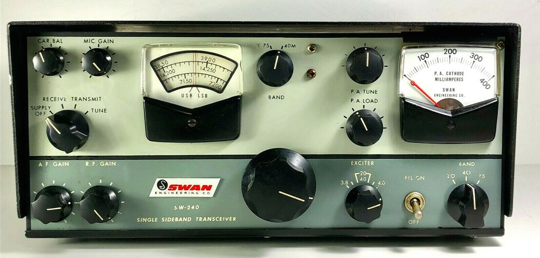
Now consider the technology and the time. Separate receivers and transmitters were how things were done. But SSB operation requires a LOT of stability of both the receiver and transmitter frequency control to work well. The answer to make SSB work easily for general amateur use was the transceiver and the only real one at that time was the KWM by Collins. Great equipment but outside the budget for many. So the time was right for a disrupter. And your recent mention of Swan is exactly that. It was started in Herb Johnson’s garage in 1962 and the first rigs were single band SSB transceivers (100 series) and well suited for mobile. These rigs also ONLY had LSB for the 80 and 40 versions and USB for 20. When you think about it, there is no technical advantage of LSB vs. USB and in fact, if both are being used, it is a distraction. Imagine doing mobile or a contest and also having to figure out which side band to be on. The military found the answer in the late 50’s by adopting the Collins equipment for the new B52 and only ever using USB. So Swan’s use of this was both a convenience and probably economic. This was the age of “Muntzing”.
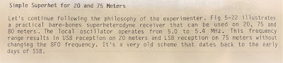
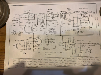
Once Swan started to take off, they added the 240 which covered 80, 40 and 20. I have attached the first page of the manual and also a clip from the schematic. The new “normal” was the sidebands as we use now and reverse was an “option”. Bill, you probably had one of the few that actually had this option installed. Later Swan radios actually included the reverse option, but regular was now titled on the front panel of many rigs by then as “normal”. So it is my belief that it was probably Swan that really is responsible for the “standard” operation as we now know. There were others of the time, but Swan was definitely an early leader in economical transceivers and produced over 80,000 during it’s existence.
Now I found in the 1970 edition of the ARRL SSB Manual on page 8 this important final clue. They note that because of some manufacturers only having a single sideband a “species of standardization on the particular sideband used in various amateur bands” had developed. BINGO, you can blame it on the appliance operators!
So our “standard” was well set by the end of the 60’s and was probably wrapped up in operating ease and product economy, and not so much for technical reasons. That is my 2 cents on this.
Enjoy and 73
Dave Wendt
VE3EAC / N9GQ
The Unicorn! A 75 LSB /20 USB Receiver (That Can’t Work)
Don’t get me wrong — I’m a huge fan of Doug DeMaw. His books and articles are a treasure trove for ham radio homebrewers. Also, Doug was an honest guy who admitted in the preface to his QRP book that at times he did not fully understand the circuits he was building; that kind of honesty is rare, and is very helpful to amateurs who struggle to understand the circuits we work on.
But everyone makes mistakes, and Doug made one in his “W1FB Design Notebook.” I present it here not as a “gotcha” effort to nitpick or sharpshoot a giant of homebrew radio, but because this error illustrates well the depth of the 75 LSB/20 USB myth, where it comes from, and how important it is to really understand sideband inversion. Here is the mistake:
That’s just wrong. A receiver built like this will not allow you to listen to 75 LSB and 20 USB “without changing the BFO frequency.” (Am I the first one to spot this error? Didn’t anyone build this thing, only to discover that it, uh, doesn’t work?)
Here’s a little drawing that I think illustrates why the mythical scheme will not work:
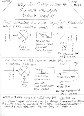
All confusion about sideband inversion could be avoided with the simple application of what I think we should call “The Hallas Rule”:
“Sideband reversal occurs in mixing only if the signal with the modulation is subtracted from the signal that isn’t modulated.”
Be careful here: I think some arithmetic carelessness is responsible for much of the myth. Taking the difference frequency is not enough to produce sideband inversion. Read the Hallas Rule carefully: For sideband inversion to occur, the signal with the modulation must be subtracted FROM the signal without the modulation.
———————————————
About the Swan 240’s SSB generation scheme:
I first stumbled on this problem when building my first SSB transmitters in the Azores. I was using a VXO, and a filter pulled out of a Swan 240 (5.173 MHz). I started with VXO crystals at around 12.94 MHz. The rig worked, but I couldn’t pull the VXO crystals very far. So I switched to crystals at around 23.3 MHz (you can pull higher frequency crystals farther). But look what happened: My Carrier Oscillator frequency had been set up to receive USB signals on 17 Meters. With the 12.94 MHz rocks, that worked fine: 18.150-12.977 = NO INVERSION. But it all changed when I went to the 23 MHz VXO rocks: 23.323-18.150 = INVERSION! This had me scratching my head a while. I had to draw myself little spectrum pictures (like the one above) before I realized what had happened. To get it to work — to get it to produce USB on 17 meters — I had to move the Carrier Oscillator to the other side of the passband. Good thing that Swan 240 came with TWO BFO crystals (5.1768 MHz and 5.1735 MHz). I just had to change the crystal.
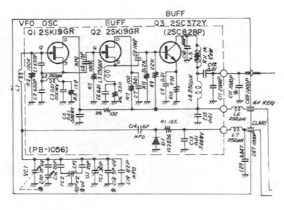
For 75 and 20 meters, the Swan 240 uses the correct 5.173 MHz filter with a 9 MHz VFO to get the happy situation of 75 meter LSB and 20 Meter USB WITHOUT changing the BFO/Carrier Oscillator frequency. This is the Mythbuster scheme. Unlike Doug’s receiver, it works. The scheme also works in the Swan 240 on 40 meters because for 40 the Swan rig has the VFO running from 12.073 MHz to 12.513 MHz. Here too, no change in the BFO/Carrier Oscillator frequency is needed. But the Swan recommended a modification that would allow operation on 20 LSB and 75/40 USB! It used a BFO/Carrier Oscillator crystal of 5.1765 MHz and a switch mounted on the front panel. Luckily, my junker Swan (acquired from HI8P in the Dominican Republic) had the second crystal — mine was 5.1768 MHz. It was that crystal that allowed me to get my Azorean SSB transmitter to work using the 23.9 MHz VXO rocks.
Ganymede and Jupiter as seen by Juno
But remember the warning:
“All these worlds are yours, except Europa. Attempt no landing there.”
Mythbuster Videos 8 and 9 — The Old Military Radio Net plus “Zero Beat and The Vertical Skirts”
I like to listen to the Old Military Radio Net on Saturday mornings. This week I was listening with the Mythbuster receiver. The AM carriers provided a good opportunity to observe the effects of the steep skirts of the 10 pole crystal filter. We start at zero beat, with the BFO exactly on the carrier frequency. If I turn the VFO dial in one direction, I in effect move the passband in a way that puts the carrier in the passband. And it is no longer zero beat with the BFO, so we hear the heterodyne (the beat!). But if I turn the VFO dial in the other direction, the carrier is now outside the passband. Even though the BFO would produce a tone, we don’t hear a tone, because those steep filter skirts are keeping the carrier out. We do continue to hear some of the sideband frequencies, because they remain in the passband. The very sharp drop-off of the carrier tone is a good indication that the steep skirts of the crystal filter are doing the job.
“Zero Beat and the Vertical Skirts” Sounds like the name of a Punk Rock band, doesn’t it? Anyway in this video I explain what happened in Mythbuster Video #8 (above). I explain why we can hear the Old Military Radio Net carriers when I tune the VFO in one direction, but not in the other.
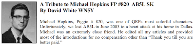
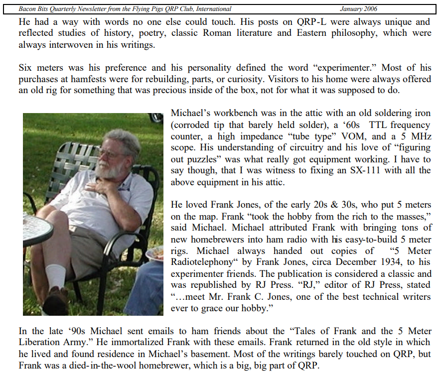
Michael Newton Hopkins, AB5L, Author of the FMLA series
Better than anyone else ever has, Michael Hopkins, in his fictional series about Frank Jones and the Five Meter Liberation Army, captures the spirit of homebrew radio. There is just so much of us in those articles. I read them some 20 years ago when they first came out; reading them again recently I appreciated them even more.
Frank was a bit of a curmudgeon: There are jabs at the appliance operators, Hiram Percy Maxim, hamfests, SSB, the Collins collectors, the QRP movement, and even Electric Radio magazine. Howard Armstrong makes an appearance, as do Carl and Jerry. It all made me want to put a five pin SAW filter on my lapel.
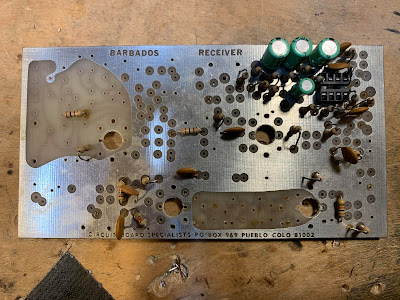
As I read, I thought about what a great writer Michael was. When I Googled him, a few of the results led me back to my own book. I’d forgotten that Michael was in there, but he is. On one page he advises me how to power my Mate for the Mighty Midget receiver without using a power transformer (a very Frank Jones approach). On another page I note that Michael had sent me a kit for the Doug DeMaw “Barbados Receiver.” Wow, that was my first Superhet. (I also have one that was built by Dale Parfitt.) Most of the parts were put to use in other projects. But I still have the board (see above). Reminded that it came from Michael, I will now have to complete the construction.
Below is a nice article about Michael that appeared in the Flying Pigs newsletter. (Click on the images for an easier read.)
The articles can be found here:
Michael’s 2005 Obituary:
Thank you Michael. VIVA EL FMLA!
Alan Wolke W2AEW’s Great Video on Using NanoVNA to Measure Amplifier Input Impedance and Gain
Alan Wolke W2AEW is a true wizard. We are all lucky to be interested in homebrew radio at the same time that he is sharing his knowledge and wisdom via YouTube.
The ability of the NanoVNA to measure circuit impedances is, in my mind, one of its most valuable features. With this, we can MEASURE input and output impedances. We can put bits and pieces of circuitry together without wondering whether or not we were introducing impedance mismatches.
But I had trouble getting good NanoVNA impedance readings on my TIA amps. I wrote to Alan about this and he pledged to make a video about how to do it right. That video was posted to YouTube today (see above).
Not only did I learn how to get a good impedance reading, I really learned a lot by just watching Alan move around through the various NanoVNA screens. I want to be able to do that too! I want to monitor the Smith Chart, and gain, and SWR, all at the same time. Yes I do! I also now realize that I have to order a bunch of those cool PC board SMA female connectors from Bezos.
Thanks a lot Alan.
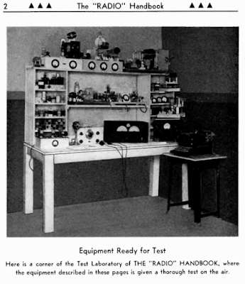
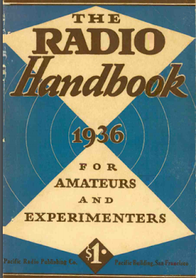
Frank Jones’s 1936 Radio Handbook
Mythbuster Video #7: Bandswitch, Reverse Polarity Protection, CW with Clarifier Offset
I have the speaker mounted on the front of the board. I kind of like it like that. I now have a bandswitch, and reverse polarity protection (no more living dangerously for me). That Yaesu VFO clarifier circuit might prove useful should I decide to give this rig CW capability. I once again find myself thinking that I might never put this in a metal box. Frank Jones had the right idea.
Mythbuster Video #6 — On to 20 Meters (But With Bandpass Filter Woes). Please help solve the mystery!
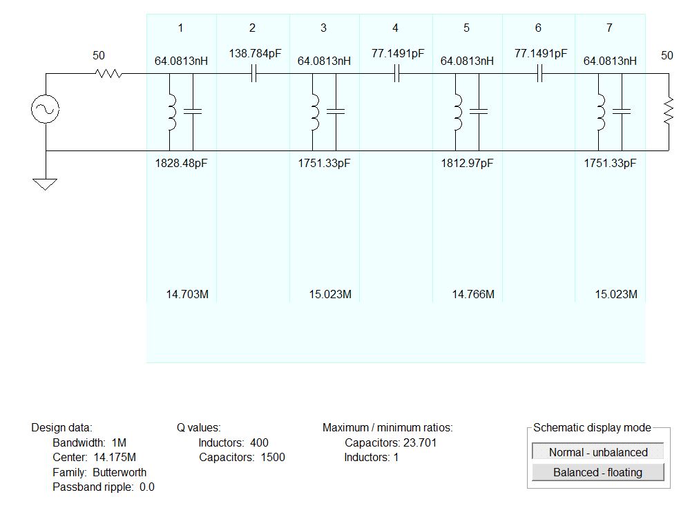
Here’s how I started with the Elsie program. Note that to get a 50 ohm match on both ends it needs an impractically low value for the coils (.064 uH).
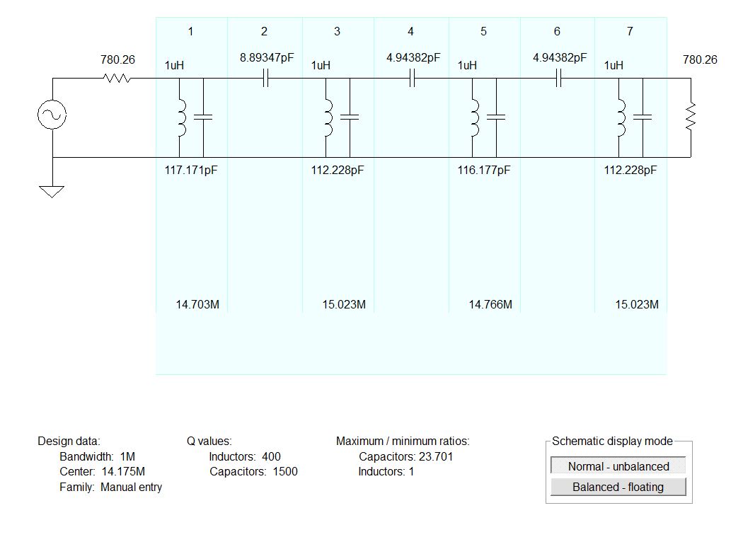
But Elsie lets you specify the coil value. So I then I went with 1 uH. But with this value you don’t get 50 ohms at either end. You need a matching network. Elsie provides this too!
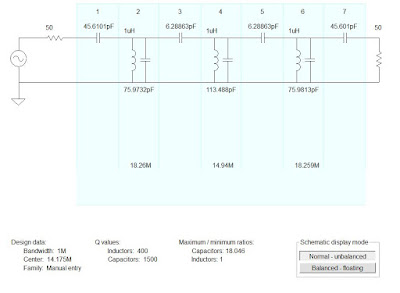
I asked Elsie to match my BP filter to 50 ohms. It provided several options to do this — I went with a simple capacitive impedance divider. But alas, I was now bumping up against the 7 limit of the free version of Elsie so I had to reduce the number of LC elements from 4 to 3. Bummer.
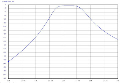
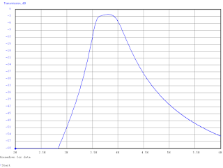
With 3 LC tuned circuits and matched to 50 ohms the plot looks OK. But I would have preferred 4 LC circuits.
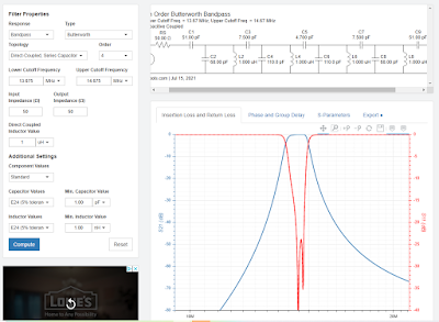
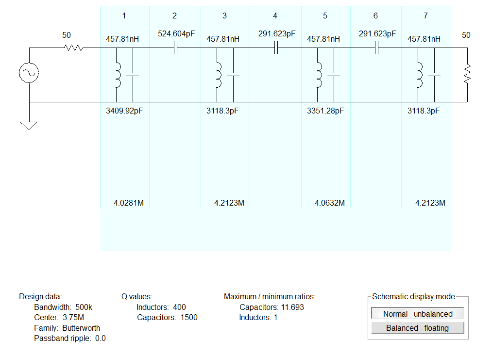
The rftools website created a BP filter for me with 4 LC elements, and matched to 50 ohms. Very useful. https://rf-tools.com/lc-filter/
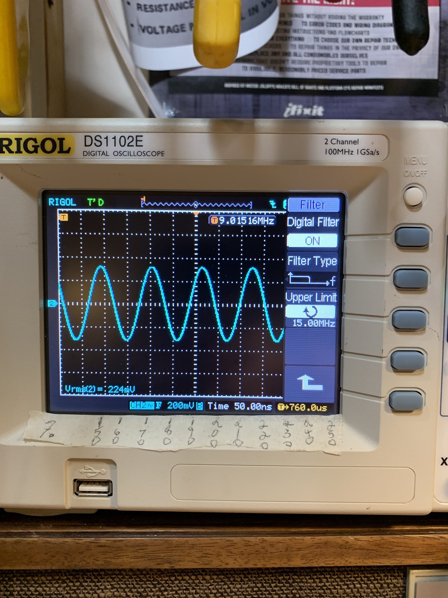
But here’s my problem: With both the filter designed by Elsie and the one designed by rftools, I found that the filter passband was too low. It was in the 12 – 13 MHz range. I found that by removing 3 turns from the 1 uH coils I could move the passband up to the desired range. But why the discrepancy? I was measuring the coils and the caps with an AADE meter. I was testing the passband both with a NanoVNA and with a combination of an HP8640B sig gen and a Rigol oscilloscope (with the filter terminated into a 50 ohm resistor). Any suggestions on why these filters should have passbands lower than predicted would be appreciated.
Mythbuster Video #5 — More Listening on 75
Mythbuster Video #4 — First Signals, 75 meter Bandpass Filter, Yaesu VFO output
This receiver required almost no coaxing or tweaking, probably because I had been so careful about testing and measuring each of the stages.
I have been pleasantly surprised at how well the receiver works without an RF amplifier ahead of the first mixer. But I need to know how much AF gain I have in order to understand how/why the entire receiver works so well. I think I have about 35 db of gain (combined) through the two TIAs and the crystal filter. That would mean that all of the remaining gain is provided by the AF amplifiers (with some loss in the product detector). I haven’t really measured the gain of the AF preamp/LM386 combo, and I had some trouble measuring the input impedance of the pre-amp with the NanoVNA.
The 75 meter LC filter to the left of the VFO is actually a bandpass filter, not the lowpass filter. And what I call “the mixer” to the right of the VFO is really the Product Detector/BFO.
For the 75 meter bandpass filter, I used the ELSIE program.
75 meter Bandpass Filter designed in Elsie. 10 turns on a T50-2 toroid yield .46uH.
Here’s the plot from Elsie on the 75 meter BP filter.
Alan W2AEW asked for a picture of the VFO output.
On this shot I had the probe between theVFO and the
outboard booster amp that I built to bring it to 7dbm.
Mythbuster Video #3 — Using the VFO from a Yaesu FT-101
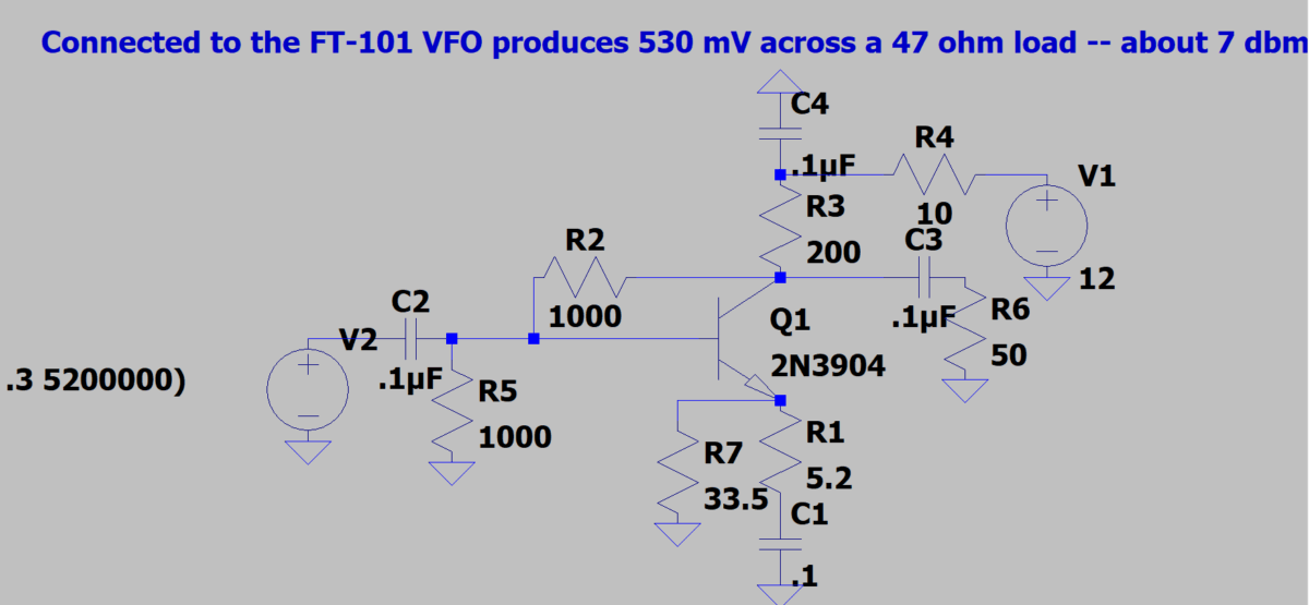
FT-101 VFO

I used LTSpice and Wes’s FBA program (from LADPAC) to come up with a circuit that would provide the needed gain. I needed to get the 290 mV rms signal (across a 50 0hm load) up to the 500 mV rms signal needed by the ADE1 mixer. Above is the amplifier that I came up with. The key here is to adjust R2 and R1 to get the required gain.