Dennis WC8C is the event coordinator for the radio club in Michigan that I recently spoke with. He mentioned to me that he was working on a homebrew 6 meter rig. FB Dennis. I see lots of tribal wisdom in your approach, especially in your decision to do this in a stage-by-stage modular form.
Dennis’s rig is obviously a work in progress, so if anyone out there has any helpful hints (especially on the carrier suppression and on the testing for spurs and splatter) please share them with him via e-mail or blog post.
Thanks Dennis!
—————-
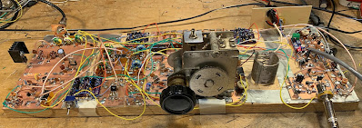
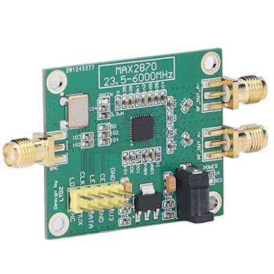
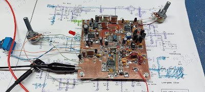
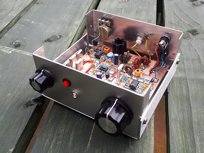
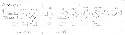
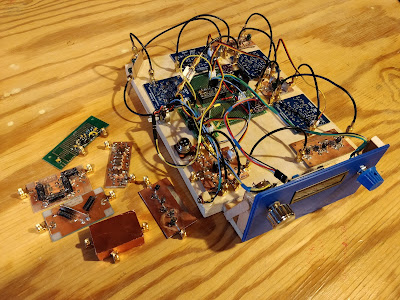
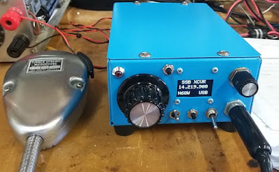
This is my 6 Meter homebrew transceiver, currently work in progress. It is a single conversion super –heterodyne design. I constructed each stage independently with SMA connectors. This is so I can re-make sections as needed, and will allow me in the future to swap sections to experiment with alternate designs. The VFO and BFO are controlled using a SI5351 with an Arduino micro controller. I currently have separate SI5351 modules for VFO and BFO because I suspected issues with cross-talk. These issues may not actually be real, so once I am happy with the performance, I will test again with just one module to see if it is OK. The Power Amp is still on the to-do list, so output is well under 0 DBm
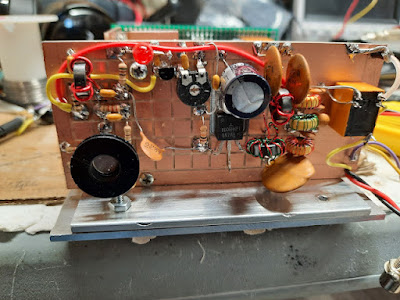
The Blue boards were designed by me and ordered on-line. The other boards I etched myself. Construction is mostly surface mount because I find it easier than drilling all the holes. SMD components are mostly 805 and 1206 size. Transistors are SOT23.
The Band Pass filter is a 5 coil design made with air-core inductors.
3 bi-directional termination insensitive (TIA) amps are used (blue boards). Total RX gain is about 44db. Total TX gain is about 16db. Each board has its own independent RX/TX switching circuitry (mosfet based) and is fed with +12.5, GND, and RX/TX logic signal from the Arduino (3V logic and up will work)
The Mixer and modulator are both Diode Ring mixers.
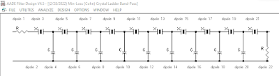
The 12 MHz SSB filter is a crystal ladder filter similar to the one used in the uBitx.
The Mic and audio pre-amp (also a blue board) is made on a modified TIA amp board. I had 10 of these boards made, and the needed circuitry was largely the same, so I modified the board with a rotary tool and jumpers.
The Audio amp is a PAM8403 module and drives a headset. I did make some modifications to the module so it runs in-spec and to eliminate the power on audio pop.
The challenges I have been having are mostly related to spurs, splatter, carrier suppression and TX audio quality. I have been gradually tweaking these things to improve operation before I start on a power amp. My IF is 12 MHZ, and I was using the LSB side of the crystal filter because it is sharper (VFO 62 – 66 MHz) but have recently changed over to the USB side of the filter (VFO 38 – 42 MHz). This eliminated the spurs I was seeing near the pass band. I still need to make some adjustments to the crystal filter as it is too broad.
I still have some splatter and audio quality seems low, but I am starting to doubt my test setup. I see the splatter on the RTL SDR, but I don’t see it on the Tiny SA. The spatter happens at ~160 KHz intervals. I am hoping to find someone local with a better spectrum analyzer to help me verify if it is the rig or my SDR dongle/test setup.
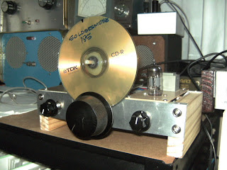
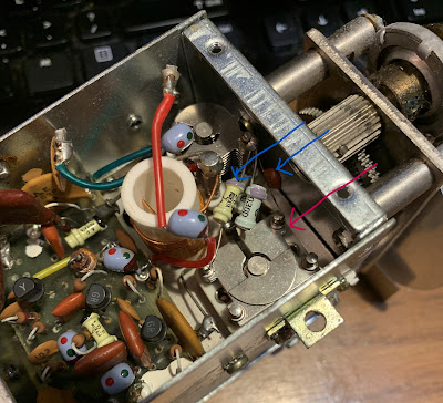
The modules to the side of the picture are my rejects/experiments. The one covered in copper shows how I eventually will shield all the modules. I 3D printed a cover for the board, when wrapped it with copper tape, soldered to the bottom ground plane. The one shown is a diode ring modulator. For some unknown reason the carrier suppression is rather poor. I had previously made a junk-box modulator that had much better carrier suppression. I don’t know why it is better than the one I more carefully made for the radio, but until I figure it out, I am using the junk box version. The junk box modulator uses unmatched schottkey diodes, whereas the “final” one uses a 4 diode SMD package because I wanted them matched – I thought this would be better, but maybe not.