
This guy has some amazing tools, and even more amazing skills. I find it inspirational to occasionally take a look at other kinds of workshops. Check it out. Video above.
Along similar lines, the young Englishman Leo was in Washington state with his girlfriend when the lock-down and travel bans kicked in, so his work on Tally Ho (and his videos) continue. See:
https://youtu.be/zXV0ywqj7zY
SITS! or Stay in the wood-shop!
Author: Peter Marks
Brace Yourselves: DK7IH’s New Transceiver — The Gimme Five
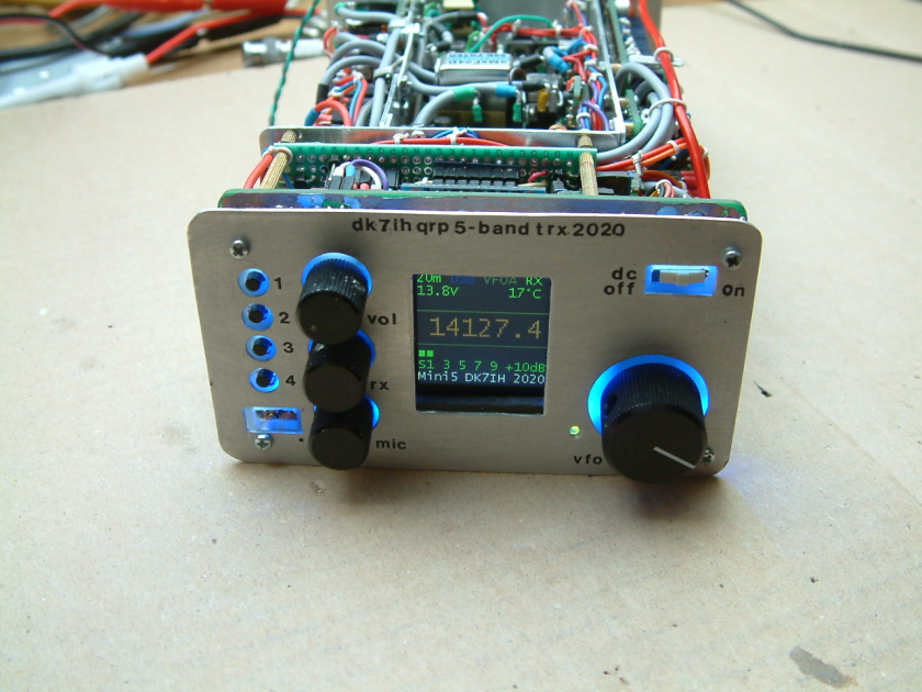
Lock-down is bad enough, but now we will also have to cope with the feelings of homebrew inadequacy that Peter’s rigs always cause. But look on this as an opportunity for inspiration. Peter once again raises the bar.
This looks like it is the first in a series of blog posts. Just what we need in quarantine. Thanks Peter.
Videos on the Q-31 Quarantine AM SW Receiver Project (and some pictures)
I’ve been making some short, stage-by-stage videos of my Q-31 receiver project. So far I have seven videos. They are here:
https://www.youtube.com/user/M0HBR/videos
Please subscribe to my YouTube Channel. And give me some “thumbs up” if you like the videos.
Thanks. SITS! FlattenTheCurve! 73
 |
| Pads from Pete, toroids from Farhan |
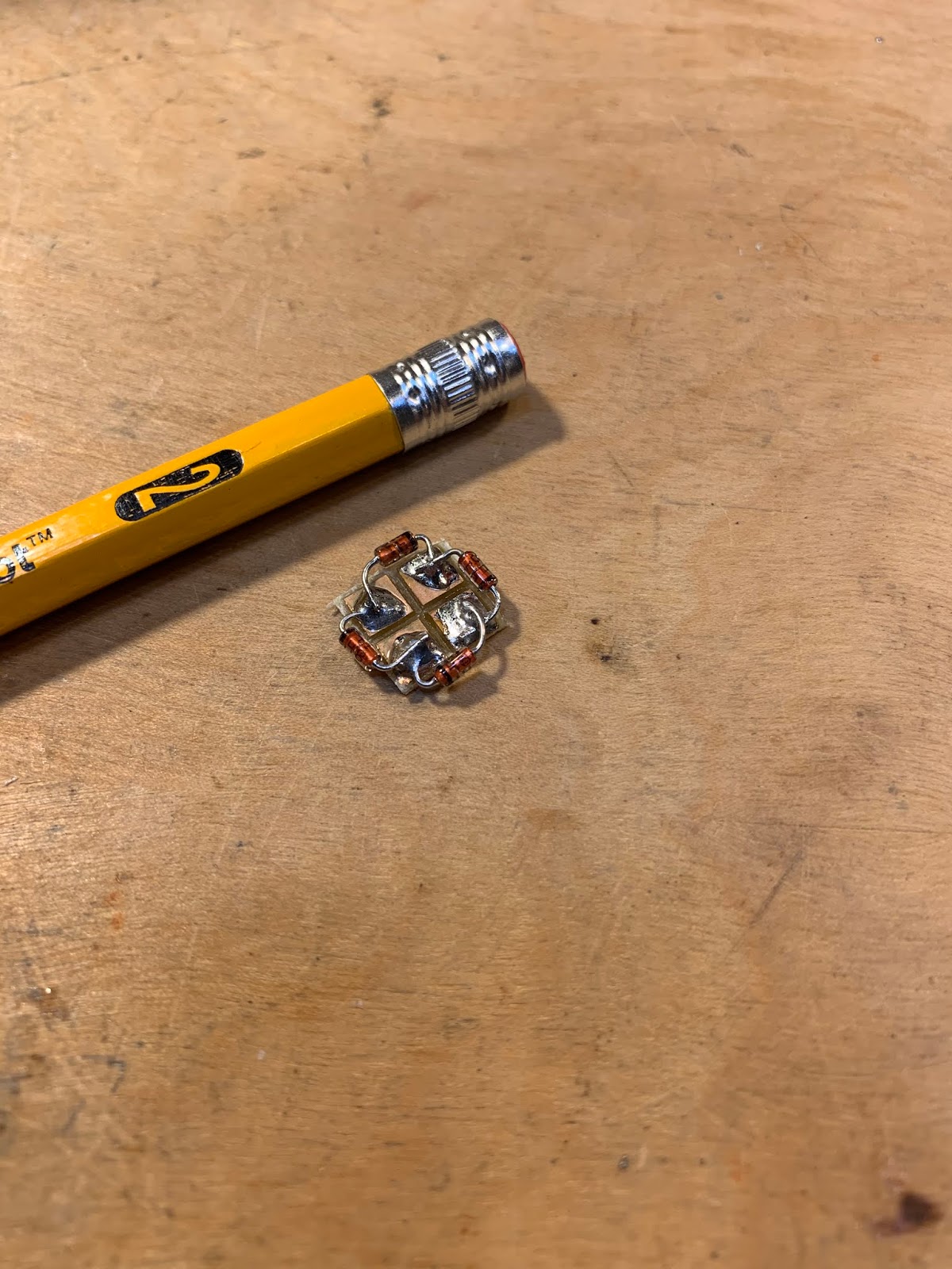 |
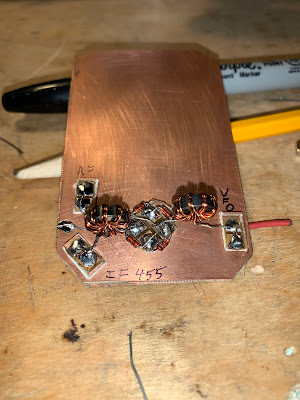
| The diode ring |
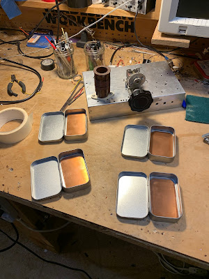 |
| Altoids-sized tins will hold the circuit boards |
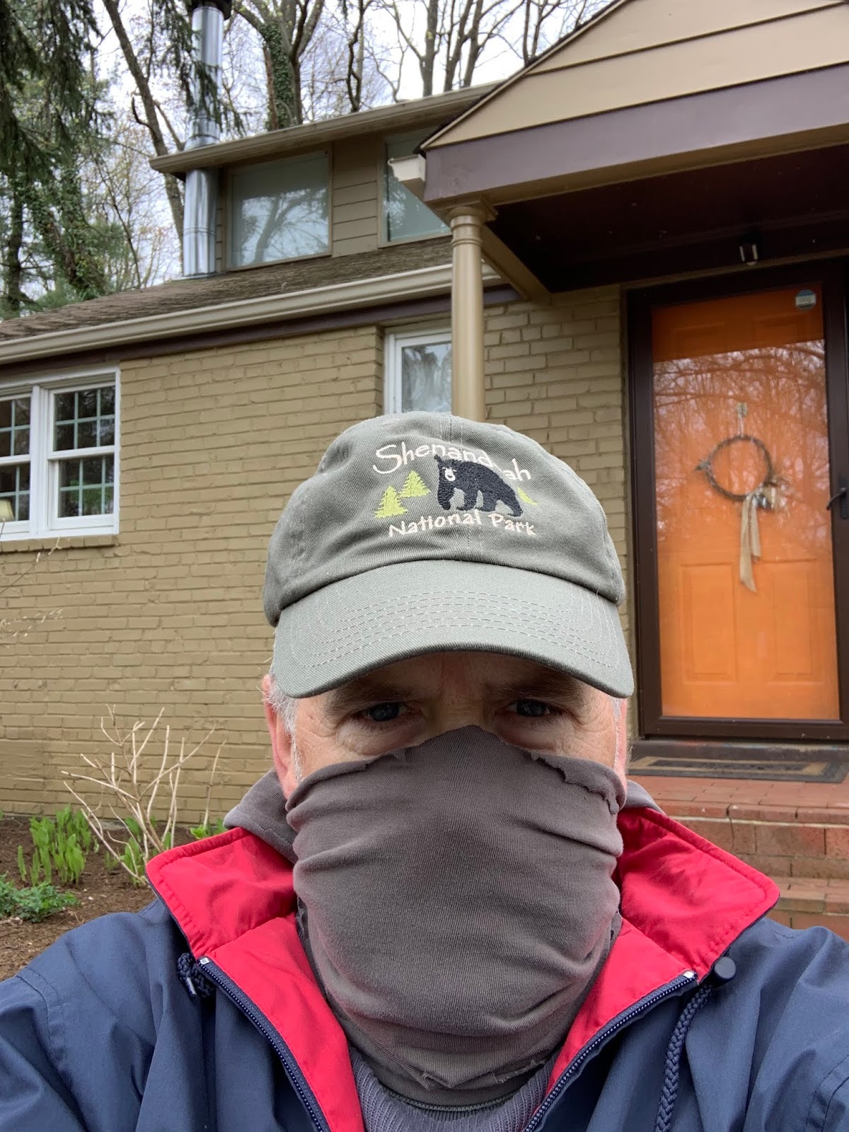 |
| Stay In The Shack — Or in the front yard. |
Blog — “Chinese Electronics Products Tested”
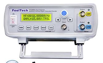
I was looking for information on my FeelTech FY3200s Signal Generator. I came across a very informative blog; it covers a variety of other Chinese gear and parts.
Here is the Feeltech FY3200S article:
https://chinese-electronics-products-tested.blogspot.com/p/fy3200s-function-generator-tested.html
Here is the home page of the blog:
https://chinese-electronics-products-tested.blogspot.com/
And here is backround information on the author:

Thanks Jos!
WB9IWT’s Quarantine Mighty Mite and N3FJZ’s “Hiram Percy Maxim Recognition Factor”
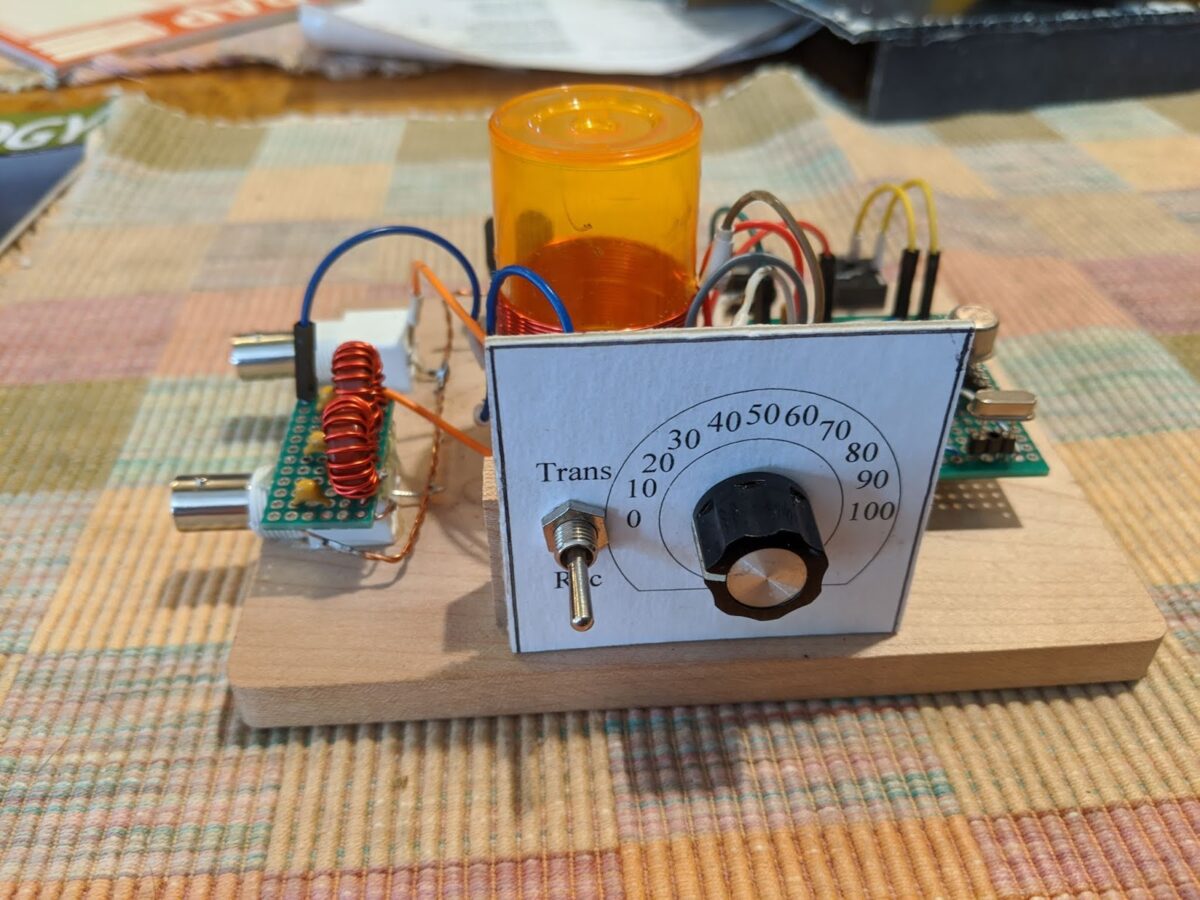

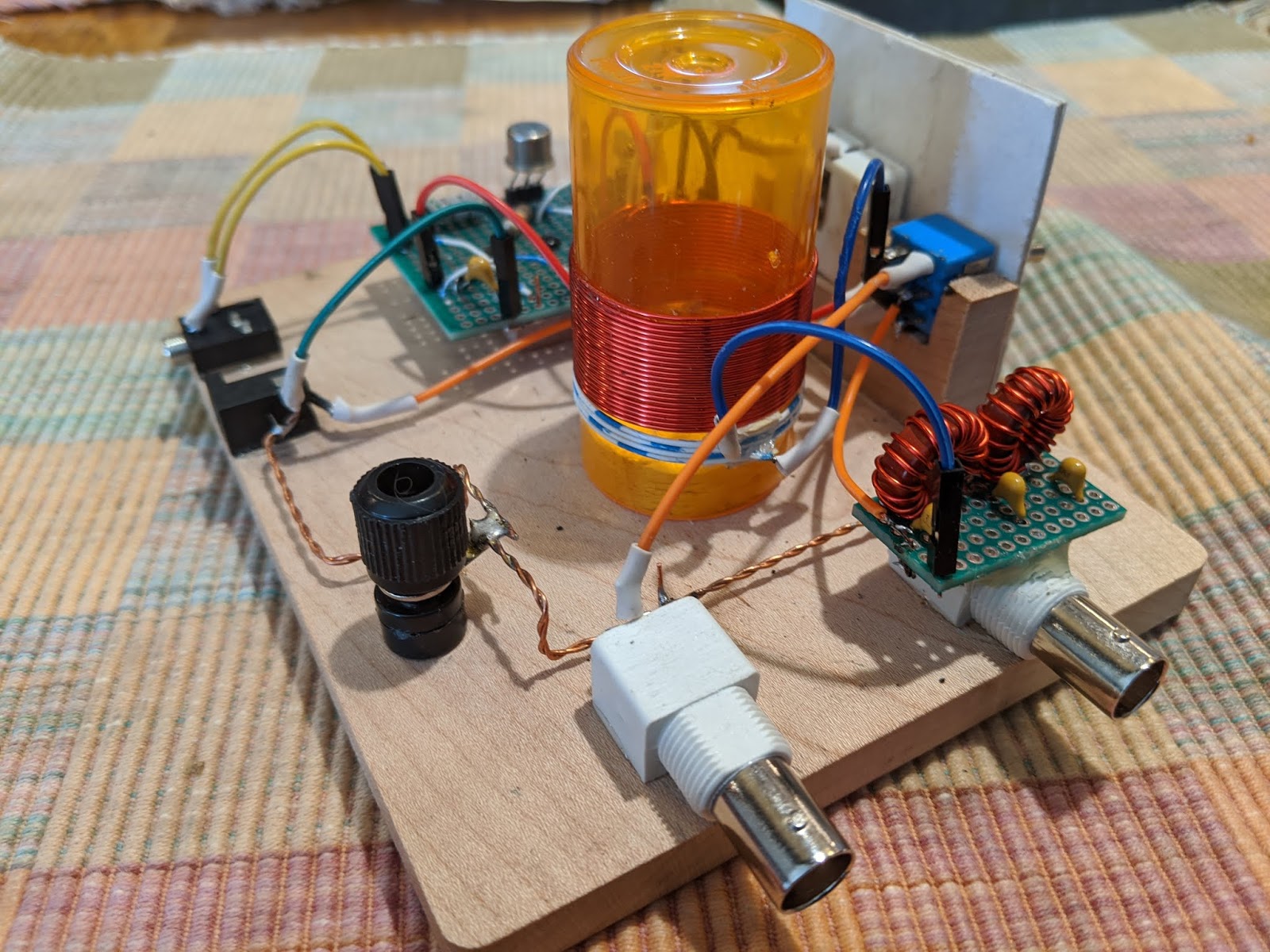
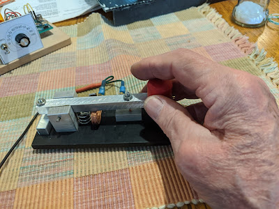
Leif WB9IWT has, during the emergency, been working on a Michigan Mighty Mite (See pictures above and below). FB Leif.
But also check out the very astute comment from Rick N3FJZ (below) . I am, of course, all in favor of the HPMR Factor. Almost all of my rigs would score quite high. Others, I know, would seek a low score. To each his own. This is all for fun.
Leif,
Great work. If a ham from the 1920’s were to see this rig, they
probably wouldn’t recognize the actual components right away (but
knowing hams, they would no doubt figure it out), but the breadboard
layout circuit flow would be immediately recognizable; e.g. the plug-in
crystal, the coil, binding post. The transistor and variable capacitor
may baffle them at first, but seeing there are three leads on the
transistor would start to give them clues.
That’s the cool part about analog discrete component radio, no matter
how many years go by, and the appearance and size of the actual
components change, the physics of what’s going on at the electron level
stays the same (SDR not withstanding).
I guess this could be a litmus test for us analog radio builders. It
could be called the “Hiram Percy Maxim Recognition Factor” or “HPMR
Factor” with a range of 0 to 1. After you build your rig, take a look
at it and pretend that you could present it to Mr. Maxim and the more he
could understand the circuits, components and circuit flow on his own,
the closer to a factor of 1 your radio would achieve. For example, an
SDR might only achieve a factor of .1 or even maybe 0, where as your rig
may achieve a factor of .8, and one of your crystal receivers would
definitely get a 1.
Someone could even workout a check list or formula where you would add
or subtract some fractional numeric values for each component you used;
e.g. you would subtract some value for every IC chip, microprocessor or
LCD display you use, and add some fractional value for each hand wound
coil, vacuum tube/valve or open air variable capacitor, et cetera.
Fun to think about.
Keep building.
Rick – N3FJZ
Quarantine Reading: Tribal Knowledge: Two Gems from Pete Juliano N6QW
WB9FLW recently reminded us of two very useful documents that have been kind of buried on one of Pete’s web sites. I think these documents are just the kind of thing we all need during these dark days of quarantine. So just sit back, StayInTheShack, and soak up tribal wisdom from the Wizard of Newbury Park.
Here is the message from WB9FLW that unearthed these gems:
Morning Pete,
Three cheers for posting the Simple SSB Transceiver as a possible project during the pandemic lockdown.
Suggestion, folks that are new to your Website may not have seen some of your earlier posts especially on jesssystems.com.
“Homebrewing For QRP SSB” is a gem and a great lead in to the simple SSB Transceiver project.
There is a lot of wisdom in those pages, perhaps you can add a link for those interested in building the rig.
“How To Stuff A Junk Box” is good as well.
Hope you and the family are doing well.
Pete WB9FLW
ZL2CTM Charlie Morris on “QSO Today” with Eric Guth 4Z1UG
Eric Guth 4Z1UG had a really nice interview with our friend Charlie Morris ZL2CTM. Charlie shared with Eric a lot of wisdom about how to homebrew radio gear. I especially liked Charlie’s comments on keeping most of his rigs on the wooden prototype boards. He said something important when he talked about the benefits of taking a break from a difficult problem, then coming back to it with a rested and refreshed mind. I noted, however, that he said most of these frustrating problems have to do with software.
I got got several chuckles out of Charlie’s comments on the difficulty of building stable analog LC VFOs (here he seemed to be channeling our good friend Pete Juliano). I chuckled because as I listened I was happily building the analog LC VFO for my Q-31 Quarantine receiver. The centerpiece of this project is a variable capacitor that Pete gave me; Pete took it out of an old Galaxy V transceiver. Believe me guys, no rotary encoder could possibly look as nice or have as much soul as that capacitor from Pete, with all its gears, reduction drives, and anti-backlash mechanisms. It even smells of machine oil. Call me a Luddite, but I will stick with the coils and capacitors.
Listen to the interview here:
https://www.qsotoday.com/podcasts/zl2ctm
Thanks to Charlie and Eric.
The Low-Cost, Open Source COVID-19 Ventilator that Farhan is Helping to Build (Video)
While many of us are just trying to pass the time by building Quarantine ham radio rigs, our good friend Farhan VU2ESE has been hard at work on a really serious project: He has been working out how to use an Arduino microcontroller as the electronic core of a simple ventilator that could save thousands of lives in the current crisis. See video above.
Here is background info on the project (from ARRL):
03/23/2020
Amateur radio volunteers from around the world have volunteered to assist University of Florida Professor Sam Lampotang and his engineering team in their quest to rapidly develop an open-source, low-cost patient ventilator that can be built anywhere from such commonly available components as PVC pipe and lawn-sprinkler valves. The amateur radio volunteers are developing Arduino-based control software that will set the respiratory rate and other key parameters in treating critically ill coronavirus victims.
Multiple volunteers responding to a call for help from Gordon Gibby, MD, KX4Z, included noted software developer Jack Purdum, W8TEE, and uBITX transceiver maker Ashhar Farhan, VU2ESE. University of Florida physicians are working to address the critical legal aspects as the design moves closer to fruition.
The ventilator’s valves would precisely time compressed oxygen flow into patient breathing circuits under Arduino control, allowing exhausted patients with “stiff” lungs impacted by viral pneumonia to survive until their body can clear the infection. The software design team is also adding simple features such as an LCD display, encoders to choose parameters, and watchdog safety features. — Thanks to Gordon Gibby, KX4Z
It is important realize that in countries around the world, many victims of COVID-19 will have no hope of getting anywhere near the kind of $50,000 ventilators found in U.S. or European hospitals. That is one of the things that makes this low cost, open-source project so important.
More details on the project here:
https://github.com/afarhan/osventproto
Please pass the word on this project. Please forward on Facebook, Re-tweet, etc.
Quarantine Project: An AM Receiver for the 31 Meter Band. The Q-31.

During this StayInTheShack (SITS) emergency, it is good to have something to work on. I decided it would be best to try to build something using only items currently in my parts collection. I’ve been getting into shortwave listening again, and I’ve discovered that the 31 meter band (9.4 – 9.9 MHz) is my favorite. Thus the “Quarantine On-Hand 31 Meter AM Receiver.” A big part of the inspiration for this project comes from the AM receiver of Paul VK3HN.
I propose that we all designate rigs built during quarantine as “Q” rigs. This will be the Q-31.
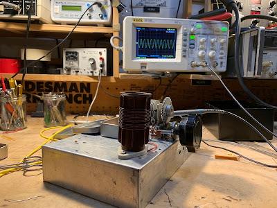
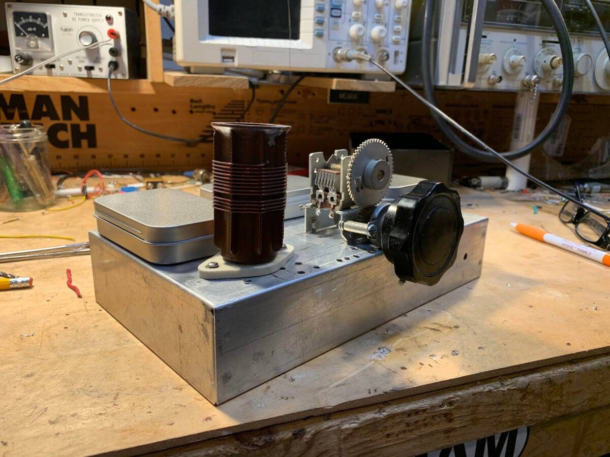
I had an old chassis on the shelf. It held my WSPR DSB rig in Rome, and various other projects over the years. It has so many holes in it that it looks like it has been used for target practice.
A while back Pete N6QW sent me this really magnificent variable capacitor with at least two reduction dries and an anti-backlash gear. I’ve been looking for a project that will allow me to use AND display this beautiful part. It will be the main tuning cap for the Q-39. It will stay — like the tubes in the rigs of days-gone-by — above the chassis.
While in London many years ago I picked up an old regen receiver at the Kempton Park rally. The parts are still in my junk box. A very nice 1.7 uH plug in coil (with socket) was there. That will be the main coil in the Hartley Oscillator that will be the VFO. I will add a few turns for the feedback coil (see circuit diagram below). I wonder of that Eddystone coil was around for the Blitz?
On the recommendation of our old friend Rogier (originally PA1ZZ), a few years ago Elisa got me a set of grey Altoids-sized metal boxes. I will have three of these atop the target-practice chassis (they will provide shielding and will cover up the holes):
— One will hold the bandpass filter (designed with the Elsie program) and the mixer (probably diode ring, with transformers from Farhan).
— One will hold two IF amps with a 10 kHz 455 kHz IF filter between them (thanks to Bruce KK0S for the filters).
— One will hold the AM detector and the AF amplifiers.
— A fourth box will be under the chassis and will hold all the powered parts of the VFO circuitry. I base my VFOs on this simple circuit from page 34 of Solid State Design for the Radio Amateur:
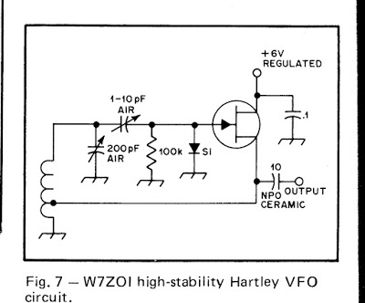
This quarantine looks like it is going to last a long time, so it is best to take your time on projects like this. I might work on the VFO today. No need to rush…
I am shooting videos as I go along and will at some point start putting them up on my YouTube channel.
So, I suggest that any of you who are feeling bored and confined (that would be almost all of us) fight back by launching a Quarantine “Q-Rig” project. Send reports to me — I will try to put them on the SolderSmoke blog.
Remember: StayInThe Shack! #SITS! #flattenthecurve.
73 Bill
SolderSmoke Podcast #220 — S-38Es, AD9833s, Pete’s Phasing Rig, FT-8
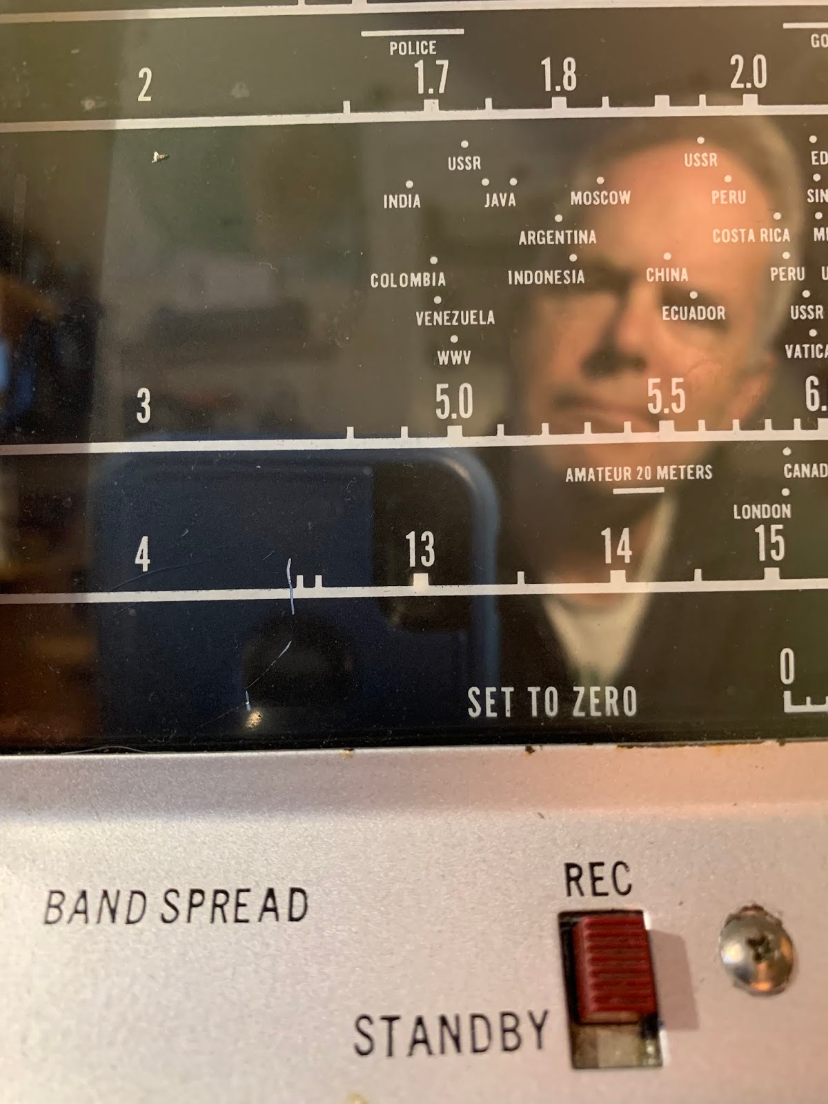 |
| Java on the S-38E Tuning Dial |
SolderSmoke Podcast #220 is available
Hunkered Down. StayInTheShack: SITS! Flatten the Curve! It is working.
Teaching English again – via Zoom. Kids completing the school year remotely.
BILL’S BENCH
— Finishing up on the S-38Es.
— I wrote up my alignment, isolation and dial string experiences.
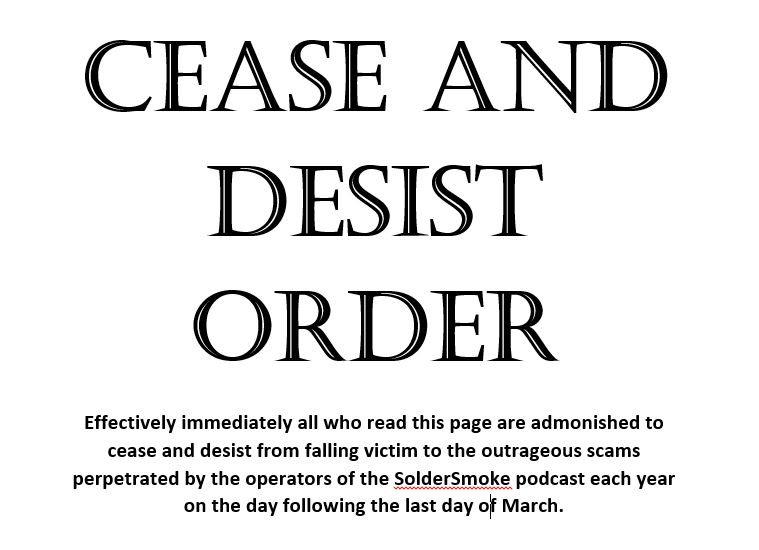
— S-38E work is causing me some serious legal problems. They are threatening to take down our sites and our podcast. Google has put a CEASE AND DESIST ORDER on my blog: Check it out https://www.homebrewradio.us/blog/wp-content/uploads/2020/04/CEASEANDDESIST.jpg
–S-38E caused me to want to get my HRO dial receiver on the SW broadcast bands with a good AM detector.
— Next up: Hayseed Hamfest cap for my Drake 2-B. And I have an idea on how to easily broaden it for AM: Tap the 455 kc output on the Q multiplier jack. 455 AM detector to audio amp.
SHAMELESS COMMERCE DIVISION
PETE’S BENCH
AD9833
Phasing Rig Project
.
DEAN’S PROJECT – Step by step. Trouble shooting. Understanding. Receiver triumph. FB.
MAILBAG
Jack 5B/AI4SV doing well in Cyprus
Daniel SA7DER listens during commute in Sweeden.
Peter VK2EMU building a 6 meter amp. With Tubes
Jim WA8ZHN says there are still 7751 Novices on the books. FB.
Mike WB2BLJ modding his BITX – having a lot of fun.
Fred KC5RT – Great idea on isolation transformer in my S-38E.
Jerry Palsson: S-38C’s curves vs. S-38E’s exotic places. Java.
Anonymous mail: FT-8 DX — Are these contacts legitimate? See below.
Dear Bill and Pete:
I’ve been meaning to share with you something that has come to my attention by a rather circuitous route.
As you guys know, I’ve been involved in the software/IT side of ham radio for many years. I’ve watched many digital modes come and go. I’ve always enjoyed my work, but lately I’ve seen something that makes me uneasy.
I’m sure you guys have heard of the fantastic DX that is being worked by many guys using FT-8. It seems like all they need to work Jakarta is a couple of watts to a wet noodle. Shazam! Contact!
Well, I learned something that calls into some question the legitimacy of many of these contacts….
As i understand it, certain manufacturers, in cahoots with a major American ham radio organization (that happens to be very dependent on ad revenue from that manufacturer), have secretly set up a system that combines the internet and ham radio.
Here is how it works: Suppose Joe Ham gets on FT-8 on 40 meters. He puts out a call using his QRP transmitter and the aforementioned wet noodle. No way that signal is going to Jakarta, right? Well, it will with a bit of help.
The system has SDR transceivers and great antennas set up at strategic points around the world — these are really great locations — think mountain tops near the coastlines, always with high speed internet T5 connections. I think this is part of the whole “contest superstation for on-line lease” business model.
One of these stations picks up Joe Ham’s FT-8 call. Sometimes it will just re-transmit it, sometimes is will send it to a counterpart station on the other side of the globe. Bingo, Joe Ham’s signal is suddenly in Jakarta. A station there enthusiastically responds, and that signal goes back with the same kind of repeater/ internet assist. This is all done out of the reach of the FCC. They are usig overseas locations, some of them in Mexico.
Of course they have to be careful not to “facilitate” these kinds of contacts during times in which the bands are obviously dead, That’s why 40 is so useful for this system. Obviously they can’t keep this kind of thing secret forever — they just want to get guys hooked on FT-8, then they can reveal the system, selling it as nothing unusual, you know, sort of akin to Echolink.
Of course, this hasn’t been made public (for obvious reasons!) but I can tell you the name of the system: They tried to make it sound like something familiar (in this case like APRS): They call it “Automatic Private Radio Internet Link 1.” My understanding is that when they do their “roll out” they will offer the new service to those willing to pay a subscription.
Obviously as an old-school, traditional ham, I’m troubled by all this. What do you guys think? I wonder what your listeners would think.
Please don’t mention my name.. But here is a site that describes the new system:
Thanks and 73…
Please let us know if you have any information on this, or have observed any unusual and suspicious success with FT-8.
Quarantine Rig: VK3YE Resurrects an Old BITX Project
I think we should start calling these “Quarantine Rigs.” Many of us are pulling off the shelves rigs that we started a while back but then put aside. Now, with the pandemic, we have the time (and the need!) to work on them.
I like Peter’s BITX receiver video, especially the part in the beginning where he wipes the grime and oxidation off the long-neglected copper-clad board.
Follow Peter’s lead: Pull those old projects off the shelf. Get them going. Now is the time. SITS! Melt solder and flatten the curve.
Thanks Peter.
Paul VK3HN’s Portable Rig
Nice work Paul.
Excellent Video on Maxwell’s Equations
Really well-done. He gets to the essence without getting bogged down in the math. Great graphics too.
How They Make Chips That No One Can Understand
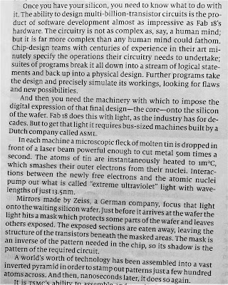
The December 21, 2019 edition of The Economist had an article about the Taiwan Semiconductor Manufacturing Company’s plant known as Fab 18. In just a few paragraphs the article explains something that I have been wondering about: We hear that some of the modern chips have millions, or even billions of transistors on them. Who could possibly design at that level of complexity? The article provides the answer: humans don’t do it. These chips are really designed by other computers (see above).
I don’t like to use integrated circuits because they often seem like mysterious black boxes I want to be able to understand how the rig I build really works. Some ICs do allow for this kind of understanding — you can get the internal wiring diagrams for an NE602, or an LM386, for example. You can study them and gain an understanding. Those little black boxes then become less mysterious. But that kind of understanding is just impossible with the kind of modern microprocessors churned out by Fab 18. No one really knows how these chips work:
“The circuitry is not as complex as, say, the human mind, but it is far more complex than any human mind could fathom.”
Sorry, but I prefer fathoming. Please pass me some 2N3904s.
Radio History Question: Why 455 kHz as the IF frequency?
My work on the S-38Es, on the HRO-dial receiver, on the Mate for the Mighty Midget, and on various mechanical filters has caused me to think (once again) about why we ended up with 455 kHz as the IF frequency for so many radios. I’ve heard many explanations for this, but unfortunately I’ve forgotten the explanations and lost the sources. I started digging into this again today. I found the below e-mail from Al N3FRQ on the Boatanchors mailing list (2008).
I contacted Al to find out if he had learned anything else on this topic. He has not. So if anyone out there has answers to Al’s questions, or anyother info that would shed light on why they went with 455, please let us know.
——————————-
Every so often the question comes up: Why are all the IF’s 455 KHz? I’d like to get an article together that solves this riddle while the people who know are still with us. I know parts of the story, but I need help with a couple of issues. There are two major consideration is the choice of the intermediate frequency used in a superheterodyne receiver. The lower the frequency, the easier it is to attain high selectivity. Also, in the early days, before tetrode and pentode tubes, it was easier to achieve a high degree of amplification at lower frequencies. Conversely, a higher IF frequency results in better image rejection. Early superhets had the IF at 100KHz or lower in order to get adequate gain from the available triode tubes. They suffer severely from “two-spot tuning” (images). By the early 1930’s, broadcast set had settled in at 175KHz, and automobile receivers would later adopt 262KHz as a standard. The advent of the short-wave craze, and multi-band broadcast receivers dictated a higher IF frequency to achieve adequate image suppression on the short-wave bands. The broadcast band occupied 550-1500KHz at this time, and the designer encounters sever problems if his radio tunes across it’s own IF. Some shortwave sets used 1600-1700KHz for better image rejection, but one couldn’t go higher if the 160-meter ham band (1800-2000KHZ) was to be covered. Most multi-band receiver settled in near 450KHz, a comfortable distance from the first broadcast channel at 550KHz. Questions: Odd multiples of 5KHz, 455, 465, etc., were usually chosen so that the image of the carrier of a broadcast-band station could be zero-beat with the carrier of the station being tuned to achieve minimal interference. (This assumes 10KHz channel spacing. Did the Europeans (9KHz) do something else?) The Radiotron Designers Handbook, Third Edition, p. 159, states “A frequency of 455 Kc/s is receiving universal acceptance as a standard frequency, and efforts are being made to maintain this frequency free from radio interference.” (1) Do FCC and international frequency allocations reflect this? (2) I’ve heard the term “Clear-Channel IF.” Can anyone cite references? (3) At lease one news group posting claims that broadcast frequencies in a particular market are assigned to prevent strong inter-modulation products from falling near 455KHz. Is this factual? Need reference.” (4) Was this (3) at least part of the reason for “Radio Moving Day” in 1941? See: http://www.dcmemories.com/RadioMovingDay/ 032341WINXFreqChange.jpg (5) Many National Radio sets used a 456KHz IF’s and I think I remember a 437 somewhere. Why? Are there different considerations for short-wave CW operation? Further input, corrections, and elaborations are greatly appreciated. Scolarly reference will be looked upon with great favor. Regards, Al -- Al Klase - N3FRQ Flemington, NJ http://www.skywaves.ar88.net/
Mr. Carlson Restores an All-American Five — Tribal Knowledge! SITS! Flattening the Curve! (video)
It is always a pleasure to see a new video on Mr. Carlson’s awesome YouTube channel, especially in these days of Staying-In-The-Shack (SITS). Obviously Mr. Carlson is doing his bit in this area. FLATTEN THE CURVE! Thanks OM!
My recent bout of S-38E madness has peaked my interest in the All American Five design, so this March 10, 2020 video was especially interesting to me. Mr. Carlson puts out so much great tribal knowledge. I didn’t know about “rounder” resistors. I didn’t know that you have to be careful not to short out (to the IF can case!) the 455 kc transformers. I really like his approach to dial cord restoration.
Mr. Carlson’s discussion of the adjustment of the front end tuner circuit on this broadcast band radio was very interesting. Unlike the S-38 radios, there are no front end coils being switched in as you change bands. In fact, it appears that that big coil/antenna inside the back cardboard piece IS the front end coil. This discussion has caused me to question my front end alignment technique for the S-38E. Did I have an appropriate antenna or antenna substitute across the antenna terminal when I set the peak on the input LC circuit? I will check on this. Hooray! One more thing to do during the COVID-19 SITS period.
UPDATE: I checked on this using the test set up described in an earlier post, but this time with my antennas connected. First with a 40 meter dipole, then with my 130 foot doublet, then with a 50 ohm dummy load I was still able to see the resonance dips at exactly where I wanted them to be.
My favorite bit of Carlsonian wisdom from this video? Mr. C’s confirmation that some hum in All American Five receivers IS NORMAL! (This may be too much for the folks who find normal band noise to be offensive.)
For Inspiration and Education: Dean’s Radio Blog (with video)
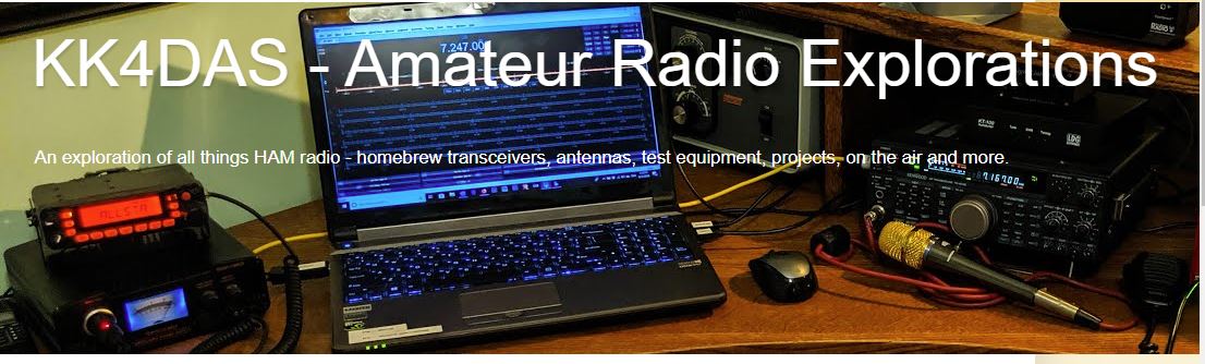
Be sure to check out the blog of Dean KK4DAS. He is a new homebrewer who is having great success with one of Pete Juliano’s ingenious SSB designs. Dean has a video of his receiver working — AL FRESCO — as construction on the full transceiver proceeds.
This is amazing. Just a short time ago Dean was taking his first steps as a homebrewer with his version of the Michigan Mighty Mite. He has followed the advice of the Tribal Wizards and has proceeded slowly, step by step, stage by stage, gaining the experience that has allowed him to actually build a superhet receiver and be on the verge of completing a full SSB transceiver.
Lots of inspiration to be found on Dean’s blog. Check it out:
https://kk4das.blogspot.com/2020/03/dean-kk4dass-furlough-40-ssb-rig.html
Technical Manual 11-455 — Radio Fundamentals — July 17, 1941
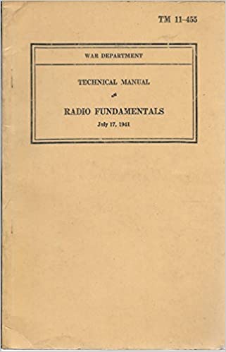
This is an illuminating little book. It was published by the U.S. War Department on July 17, 1941, less than five months before Pearl Harbor. Far from being dated, this book contains a lot of great explanations of — as the title indicates — the fundamentals of radio. I turned to it this morning for a little refresher on the physics of regenerative feedback.
You can get your own paper copy here:
Or here:
Or you can read a slightly more recent edition (1944!) online (free) here:
Please let me know if you find this book useful.
These Variable Capacitors Work — Ether or No Ether!
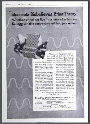
Amazing that the arguments about the presence or absence of a luminiferous ether made its way into parts advertisements in a radio magazine. This is from Radio for January 1923. (About 18 months before my dad was born.)
BTW that capacitor looks very nice, and would almost certainly still work. I have caps like that in my junk box. The shape of the blades helps address one of Pete Juliano’s complaints about analog oscillators — the inconsistent spacing of frequencies on the dial.
Thanks to the K9YA Telegram for posting this.
COVID-19 — StayInTheShack (“SITS”) — Our Contribution to Flattening the Curve
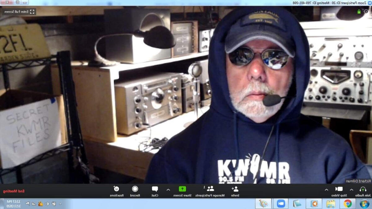
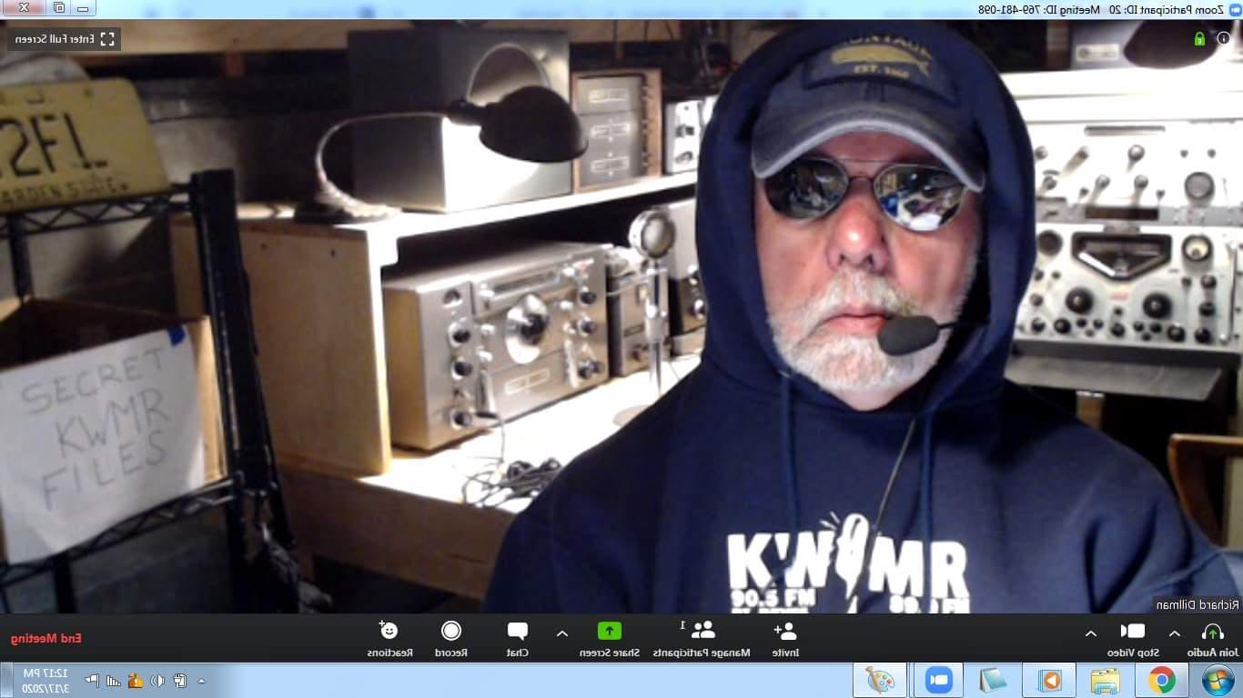
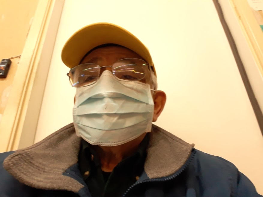
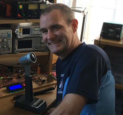
Early in the COVID-19 Emergency, I saw this inspiring picture of Dick Dillman W6AWO. Dick had placed a caption under the picture: “I’ve moved to the command bunker and will be staying here for the duration.” That’s the spirit OM! That is what we as radio amateurs should be trying to do at this point. That is how we can help flatten the curve and slow the transmission of the virus.
I guess we could call this #SITS: Stay-In-The-Shack. For many of us this is really not much of a sacrifice — this is what we mostly wanted to do anyway. And we have people to talk to (on the air).
So… Follow OM Dillman’s lead. FLATTEN THE CURVE! STAY IN THE SHACK!
73 and take care.