|
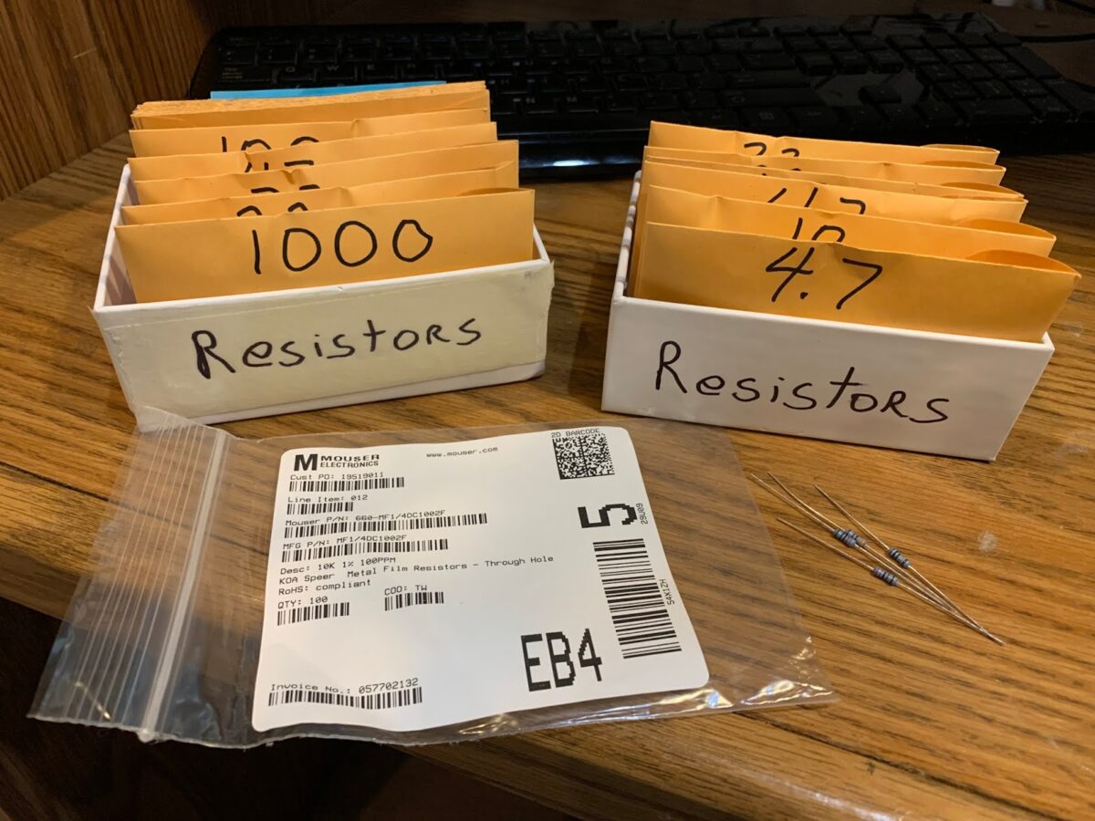
| I put the resistors in parts envelopes and cardboard boxes |
Hi Bill,
You mentioned wanting to get a resistor kit. If you’d like, I can
help you do what I did.
Then I noodled about it a bit. And looked at mouser.
A tiny bit of code put together a copy and paste list of part numbers
that I pasted onto mouser’s BOM order form. And bob’s your uncle.
In my case, a particular manufacturer’s 1/4 W metal film 100 ppm as
they were 1.9c @ 100 pieces. I created a copy and paste BOM for E6
over 4 decades plus E3 for a 5th and 1M and 49.9 ohms. Less than $2
per value for 29 values. Not a bad price for the size of the resistor
kit. I also figured if the value gap was too large, I could fill it
in with the other half of the E12 series. (E6 series is every other
E12 series value.)
This could be tweaked. Perhaps fewer resistors in each value. Or add
some more special values or whatever.
Mouser was kind enough to cut tape and put each value in a flat
plastic baggy with a label as to what was inside. Sorted in a file
box, it’s a snap to grab a resistor.
Perhaps this is something I should post online to share? Maybe
someone else already has?
On my todo list is to construct my self a homebrew BOM of capacitors.
If you’re interested, I could update this and let you know what Mouser
can do for you. It may not be your preference, but it is an
interesting option.
Best regards,
Drew
n7da
——————————–
Drew: Your message caused me to think about what I really need in a resistor kit. I have been using some other resistor kits, but I end up using ALL of certain values and NONE of others. Your message made me realize that there is valuable data in those old kit packages.
I took a look a them this morning. It seems I use the following values: 4.7, 10, 47, 100, 220, 330, 470, 1k, 2,2k, 3,3k, 4,7k, and 10k. That’s about it. So maybe I just need to go to mouser and order, 50 of each. I’m thinking 1/4 or maybe 1/2 watt?
The packaging you describe sounds great. How can I get Mouser to do that for me?
I don’t think I need the more sophisticated approach you used, but I’m sure we have listeners who could benefit from it.
Any further suggestions?
Thanks again,
73 Bill
—————————–
Hi Bill,
Sounds very good. It turned out to be simple for me to order a
ridiculously well stocked resistor kit, but doing something custom is
actually a great idea. If you want both 1/4 and 1/2, get both. (I
figured I could always make a 1/2 W resistor out of 2 1/4 watt
resistors.)
The packaging is just what they do. No extra charge other than their
regular shipping and handling.
So, I did this in late 2018. When ordered, two values were
backordered, but they shipped them out a month or 6 weeks later or
something. Checking now, 660-MF1/4DC1000F (a 1% 100 ohm metal film
1/4 watt), I see it is out of stock with an ETA of June 1st for 10K
they are ordering. The other P/N that was backordered was
660-MF1/4DC1503F. Who knew 100 and 150K ohms were extra popular?
150K is in stock right now BTW. Maybe it’s random what they run out
of?
Best thing is you copy and paste your list of P/Ns and quantity for
each and bam Mouser will tell you pricing and if anything is
backordered, etc. If you don’t like what you see, change your list
and try again.
I actually thought about what I wanted, then looked at Mouser to see
what they had and what the pricing was on it.
So, from this particular resistor family, I see the pricing is what it
was a couple of years ago.
if you order 50 pieces of that 150 or 100 ohm resistor, that is:
50*$0.055 = $2.75 for 50 resistors.
If you order 100 pieces of that 150 or 100 ohm resistor, that is:
100*$0.019 = $1.90
IT”S CHEAPER TO ORDER 100! Well, at least for this resistor family
and for Mouser’s price breaks. You have to look at the price breaks
versus volume. And of course, understand the minimum you need and the
maximum you can store in your lab. 🙂 Don’t be ordering 10,000.
🙂
So, price breaks for these they show:
Qty. Unit Price
1 $0.23
10 $0.055
100 $0.019
1,000 $0.014
2,000 $0.009
10,000 $0.008
25,000 $0.007
You can see that there’s a good break at 10, 100, and 2,000. The
quantity with a good break really depends, so you would have to look
at different vendor product families to see. I don’t think I looked
very long. I probably knew I wanted 1/4 W (may have considered 1/8 or
1/2, don’t remember). I also think I knew I wanted metal film. When
I saw the pricing on these at 100 pc and with 1% tolerance (so I could
double out to E12 series and have it make sense if it turned out to be
useful for me), I stopped shopping.
Here’s the full BOM I ordered. The top part is some extra parts I
wanted and those couple of special resistor values. The lower part
was generated by just a few lines of python:
—–
G6K-2F-Y-DC12|8
1N4007FFG|100
1N4448|100
2N3904TAR|100
2N3906TAR|100
2643000101|100
2643002402|25
2673002402|25
2661000101|25
1C10X7R104K100B|50
1C10X7R103K100B|50
ECA-1HM101|25
ECA-1HM100|25
TIP29CG|5
TIP30CG|5
1N5355BG|10
PR01000104700JR500|10
PR01000102200JR500|6
MF1/4DC1800F|20
MF1/4DC2400F|20
MF1/4DC36R5F|10
FC2053-440-A|100
MF1/4DC16R5F|20
MF1/4DC10R0F|100
MF1/4DC15R0F|100
MF1/4DC22R0F|100
MF1/4DC33R0F|100
MF1/4DC47R0F|100
MF1/4DC68R0F|100
MF1/4DC1000F|100
MF1/4DC1500F|100
MF1/4DC2200F|100
MF1/4DC3300F|100
MF1/4DC4700F|100
MF1/4DC6800F|100
MF1/4DC1001F|100
MF1/4DC1501F|100
MF1/4DC2201F|100
MF1/4DC3301F|100
MF1/4DC4701F|100
MF1/4DC6801F|100
MF1/4DC1002F|100
MF1/4DC1502F|100
MF1/4DC2202F|100
MF1/4DC3302F|100
MF1/4DC4702F|100
MF1/4DC6802F|100
MF1/4DC1003F|100
MF1/4DC1503F|100
MF1/4DC2203F|100
MF1/4DC3303F|100
MF1/4DC4703F|100
MF1/4DC6803F|100
MF1/4DC49R9F|100
MF1/4DC1004F|100
—–
So, your BOM (4.7, 10, 47, 100, 220, 330, 470, 1k, 2,2k, 3,3k, 4,7k,
and 10k) would be the following. Added the 4.7 by hand and deleted
the other values by hand. Qty 100 each.
—–
MF1/4DC4R700F|100
MF1/4DC10R0F|100
MF1/4DC47R0F|100
MF1/4DC1000F|100
MF1/4DC2200F|100
MF1/4DC3300F|100
MF1/4DC4700F|100
MF1/4DC1001F|100
MF1/4DC2201F|100
MF1/4DC3301F|100
MF1/4DC4701F|100
MF1/4DC1002F|100
—–
Mouser.com. Services & Tools button. BOM Tool button. Login (they
want account for the tools. I can’t complain.) Upload spreadsheet or
copy and paste. In this case, copy and paste. In fact, copy right
out of this draft email and into their tool. Next. Then they ask me
for a name for the BOM and if I only want RoHS. (RoHS is up to you.
I picked only RoHS, because I know all these parts are RoHS and it
won’t warn me about lead poisoning or anything.) Process BOM.
Blammo.
I had the 4.7 wrong, but they figure it out. Ouch. Pricey. Maybe
you don’t need so many, but $4.6 for 100. Parallel a couple of 10
ohm, you’ll have less parasitic L in your emitter circuit. Change the
BOM before you click the add all to cart. No problem. Or maybe 4.7
is worth the extra money to a high roller such as yourself. 🙂
2 parts are at 0 inventory. The 100 we knew about. 470 as well with
6K arriving 15June. Yes, those ETAs are perhaps questionable. Dunno.
They will ship you what they have and ship the rest later AT NO EXTRA
CHARGE. 🙂
A third part is at 123 pc inventory. Act now before they are all out!
🙂 220 ohms. 6K due end of June.
The above would be $25.50 plus less than $10 for their cheapest
shipping option. Not a bad price for a well stocked CUSTOM kit and
it’s really easy to do. And these are good parts with specifications
and tempcos etc. all in the data sheet. Sure, you don’t need it 99%
of the time, but if you wanted it, because you were doing something
fussy, you have it.
You could cut that price down quite a bit if you went carbon or wider
tolerance. (Who needs 1%? This is electrical engineering, not
mechanical engineering!) Or maybe another manufacturer. It’s easy to
browse on Mouser and figure out those other options quickly and what
it may do to help you out. Of course, when you get to a price of
$0.00, you still have the flat rate cheapest Mouser shipping as the
floor on what price you can achieve.
Mouser will also give you a print and email with price, part number,
description of everything in your custom kit. And each pouch is
labelled. Crazy! 🙂
Another crazy thing is with these BOMs is that you can easily share
them with others.
Best regards,
Drew
n7da