We have reached the point where we have to decide on an antenna for the high-school direct conversion receiver. It needs to be simple and easy. It needs to be something that students can easily install from a bedroom window in an apartment or a town house.
We thought about an End Fed Half Wave, but 66 feet of wire seemed to be too much, and the EFHW would require both coax and the construction of a transformer. That seemed like too much.
So here is what happens with just 33 feet of wire (1/4 wave on 40 meters), with another 33 feet as a counterpoise. I found that the counterpoise worked just as well spread out on the bedroom floor as it did hanging out the window along the outside of the building. As you can see in the video, the counterpoise is really necessary with this kind of antenna. It makes a big difference.
We know that the students could have dispensed with the counterpoise by connecting the copper clad boards to a cold water pipe, but that might be difficult for them. So we went with the counterpoise.
After the antenna demonstration I ramble on a bit about the high-school construction project, and where the students could go from here.
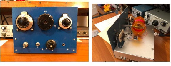
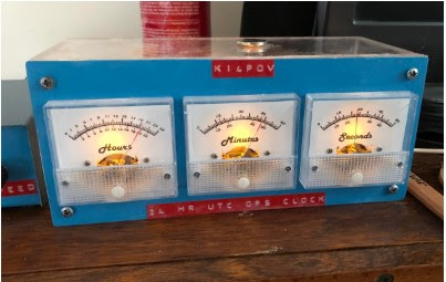
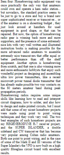
Will’s homebrew station is really something. The rig (it truly qualifies for this term of praise) is amazing all by itself (see below), but a look at Will’s QRZ page reveals other ingenious inventions and techniques: There is the clock made from panel meters. And the method he uses for making aluminum project boxes. He even made an N0WVA regen receiver. That’s the one I used in my ET-2. Fantastic.
Will really needs to share his homebrew skills with others. I hope he is soon in a local high school teaching students how to build things. Thanks Will!
Bill and Pete,
Just wanted to send a note to update you on the latest projects here. The last time I emailed, I mentioned wanting to build a superhet, which you (rightfully) discouraged, pushing for a DC receiver.
Well, I finished the superhet at the end of last year. I had most of the receiver working long before then, but got bogged down in an AGC system. The final receiver is a 5 band si5351a controlled single conversion superhet loosely based on Todd, VE7BPO’s design with several modifications. I used a 9 Mhz IF instead of 4, I used a digitally controlled LO and BFO, and as mentioned, I added an AGC system, which ended up being the most challenging (and most interesting) part. The final AGC system I ended up with used the detector and amplifier side of Wes Hayward’s “full hang” AGC from SSDRA, but I didn’t have the IC IF amplifiers with variable gain, so instead, it fed a PIN diode attenuator circuit to control the IF gain. The final result worked great, but I nearly pulled my hair out getting it to work. I originally intended to build the receiver for 40 and 20 meters, but it ended up covering 80, 40, 30, 20, and 15 since I used the filter relay board from QRP Labs which had 5 slots.
After I got the receiver running, I decided I needed a matching transmitter, so I built up a simple CW transmitter to match. It uses an si5351a VFO driving a 74HC04 hex inverter as the buffer amplifier. The trick here is that by driving all the inverter gates in parallel, the output impedance is ~14 ohms broadband, suitable for driving a BJT PA without any need for matching transformers. The PA is 3 2N2222s in parallel with heat syncs putting out about 2 watts from 80 – 15.
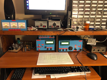
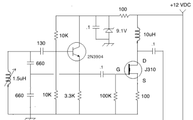
The part I’m most proud of is that I have the arduino for the receiver connected to the arduino for the transmitter through a serial line. The receiver sends it’s current frequency to the transmitter so that the transmitter can track the receiver’s frequency as you tune (like a transceiver). I’ll attach a few pictures of my homebrew station below. The transmitter is on the left, receiver is on the right. The box on top of the transmitter is my homebrew keyer. Next up on my build list is a solid state T/R switch.
Bill, I’ve enjoyed following the updates on the school DC receiver build. My local club is wanting to do some youth outreach, and I’d love to get them involved in building. I’m the only builder in the club though, so I don’t know if I personally have the manpower to make it happen. Also, thanks for the recent info and pictures of Cuban homebrew rigs. I grew up listening to Arnie Corro, so I love seeing their resourcefulness and ingenuity. Makes me want to take apart some old electronics.
Pete, I’m enjoying following the 10M SSB project. With the uptick in propagation, I’ve been bitten by the 10M bug, and I’m thinking a 10M rig may have to be on my project list for this year.
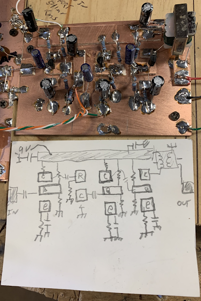
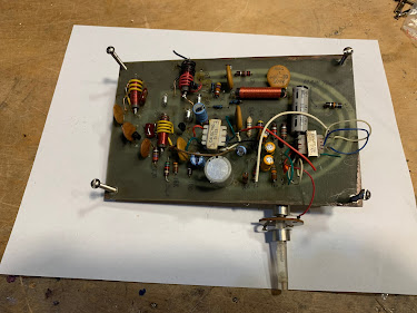
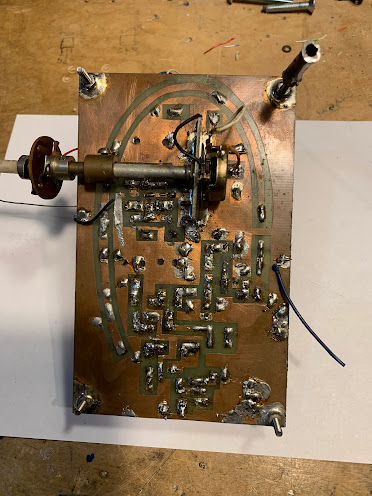
One of the receivers. (l to r) AF, PTO, Mixer, BP filter
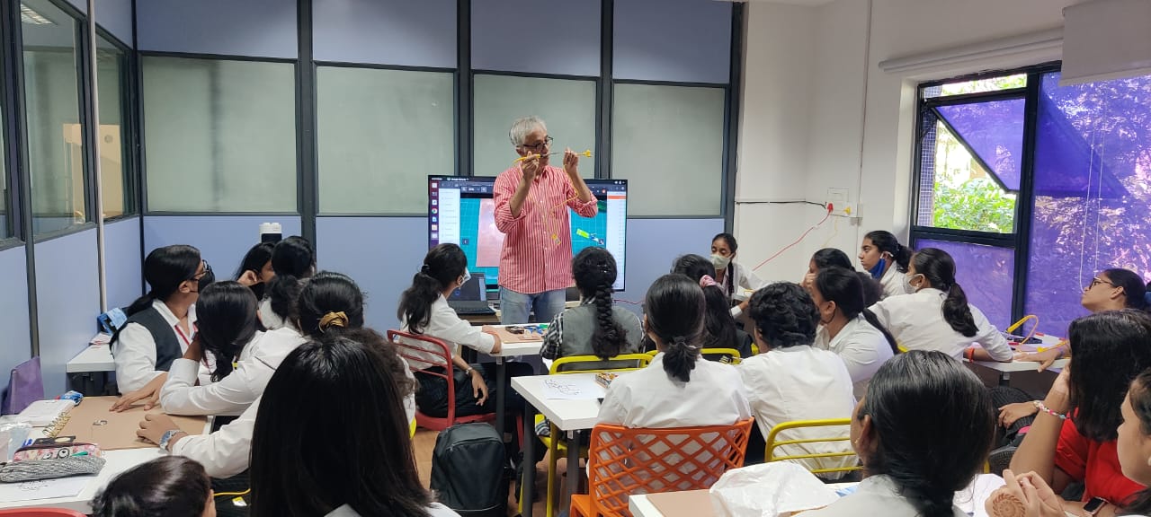
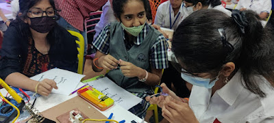
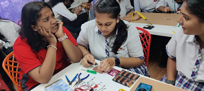
The students continue to make great progress on their direct conversion receivers. Yesterday they were enthusiastically sitting down to workbenches, building Manhattan-style circuits, working directly from schematic diagrams. It was really impressive. They are building receivers.
This week we had two sessions of about two hours each. We introduced the final board: the audio amplifier. Many of the students began work on this amplifier; others were catching up with work on boards presented earlier.
The AF amp is their most challenging board: It used 14 Manhattan pads and about 26 components. We warned the students that amplifiers often aspire to be oscillators. We told them to pay attention to layout, and to keep their leads short.
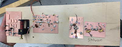
One of my builds, and a Manhattan board pattern
At first, the students just built the first stage on the AF amp board. They tested this, then moved on to build the other two stages.
By the end of Friday, two groups had completed the build of the AF amplifier board.
We think there are about 13 receivers in production. Some are near completion, others will need more work.
On Thursday of next week those teams that have completed all four boards will put the circuits together and will test the entire system. They will then add all needed front and back panels and socketry.
We really want the students to complete as many of these receivers as possible. Exam season and the end of the school year is approaching, so we have to get this done. We will remind students that they don’t want to that person who ALMOST finished a project! We will urge them to GET IT DONE! They can tweak it and mod it later. This kind of tweaking and modification is part of the homebrew experience.
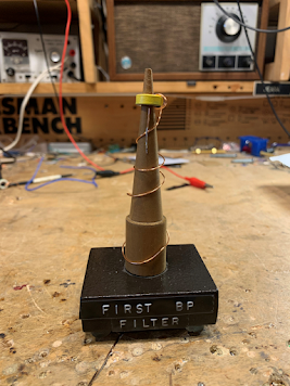
We have been presenting awards to the students who are first to complete each stage: The winners of the PTO board competition got a copy of SolderSmoke: Global Adventures in Wireless Electronics. Those who won the mixer competition got a W1REX Hamfest Buddy transmitter. Thanks Rex! And this week we presented an award to the students who were the first to complete their bandpass filter. You’ve heard of the Tony, the Emmy and the Grammy? Well, we presented “The Torry” (from Toroidal). The trophy was made from a toroidal winding tool made in Alaska by KL7FLR. I explained to the students who had made it. Thanks Paul!
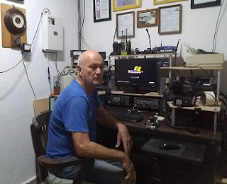
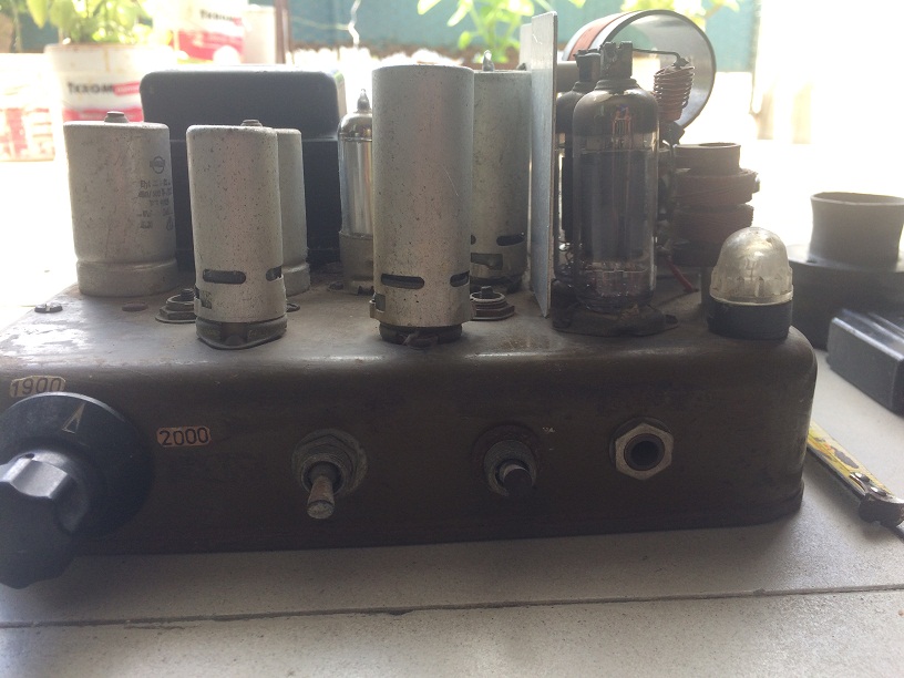
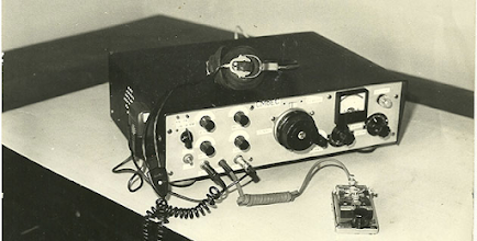
Jose CO6EC sent us more information about homebrew rigs built in Cuba. The transmitter above is a thing of beauty. I am really glad that Jose has held on to it. Thanks Jose!
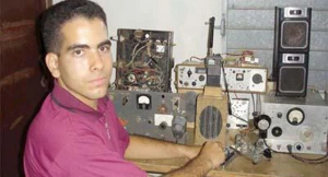
Jose CO6EC today
Jose CO6EC writes:
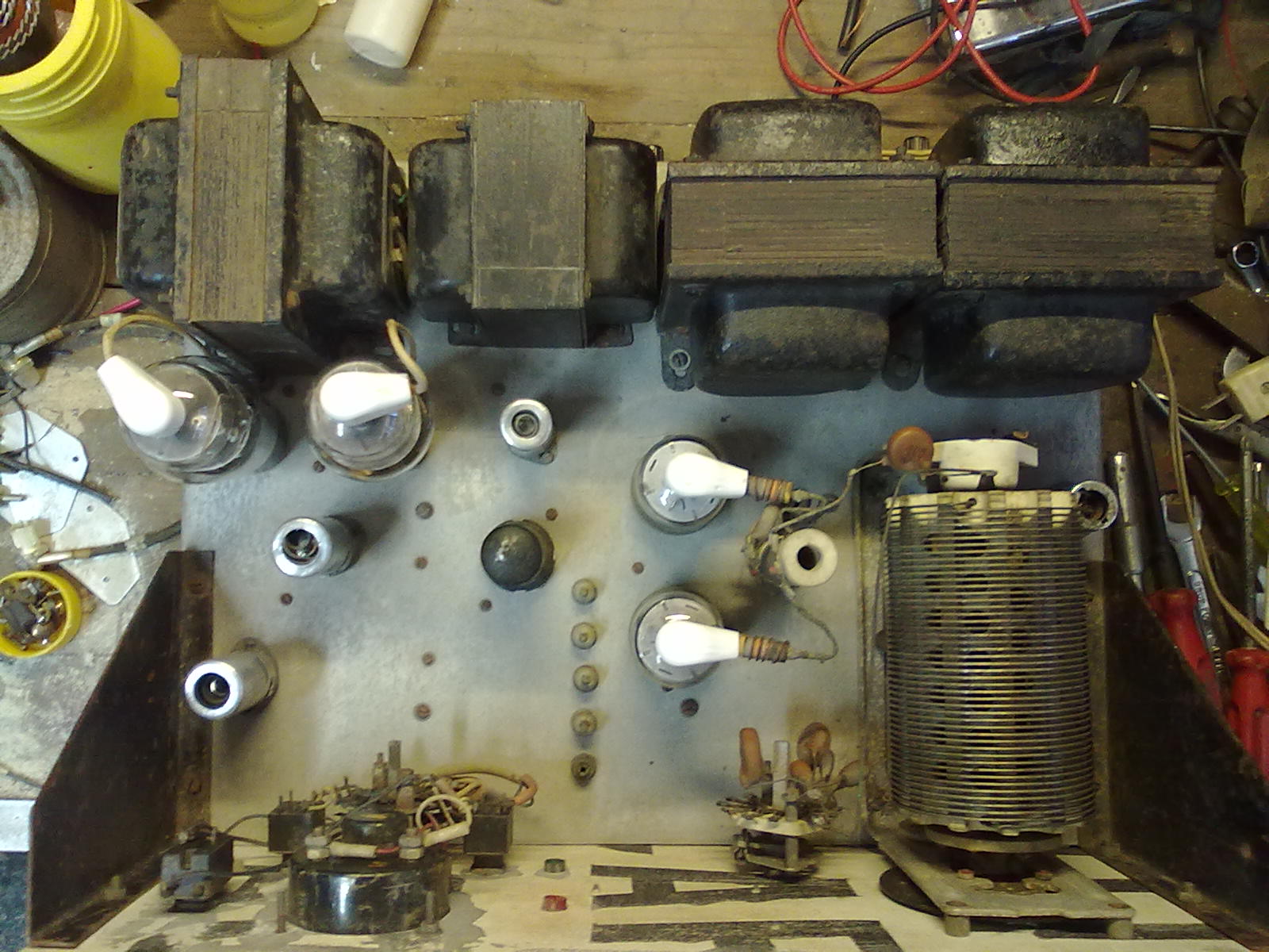
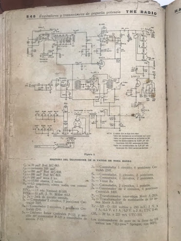
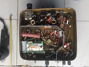
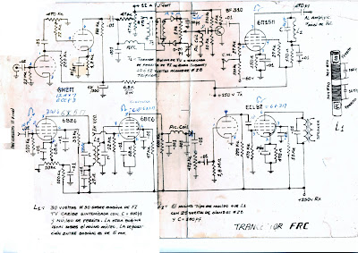
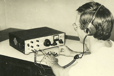
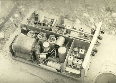
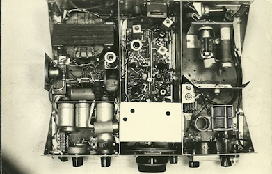
This is another work from that time: an AM and CW transmitter of about 100W of power, with an on-board modulator. It was taken with some modifications from a Handbook from the 50s. Here goes: it was built with what we had on hand at that time, it still exists, I keep it as a relic of those years.
It used combined Soviet and American tubes in the RF sections: Soviet 6P9 and (2) 6146. The modulator used Soviet 12AX7, 12AUT and (2) 6P7. The 6P9 works as a crystal oscillator, and in case of using an external VFO it works as an amplifier and doubler or tripler to obtain outputs in the 160,80,40,20,15 and 10 Meter bands.
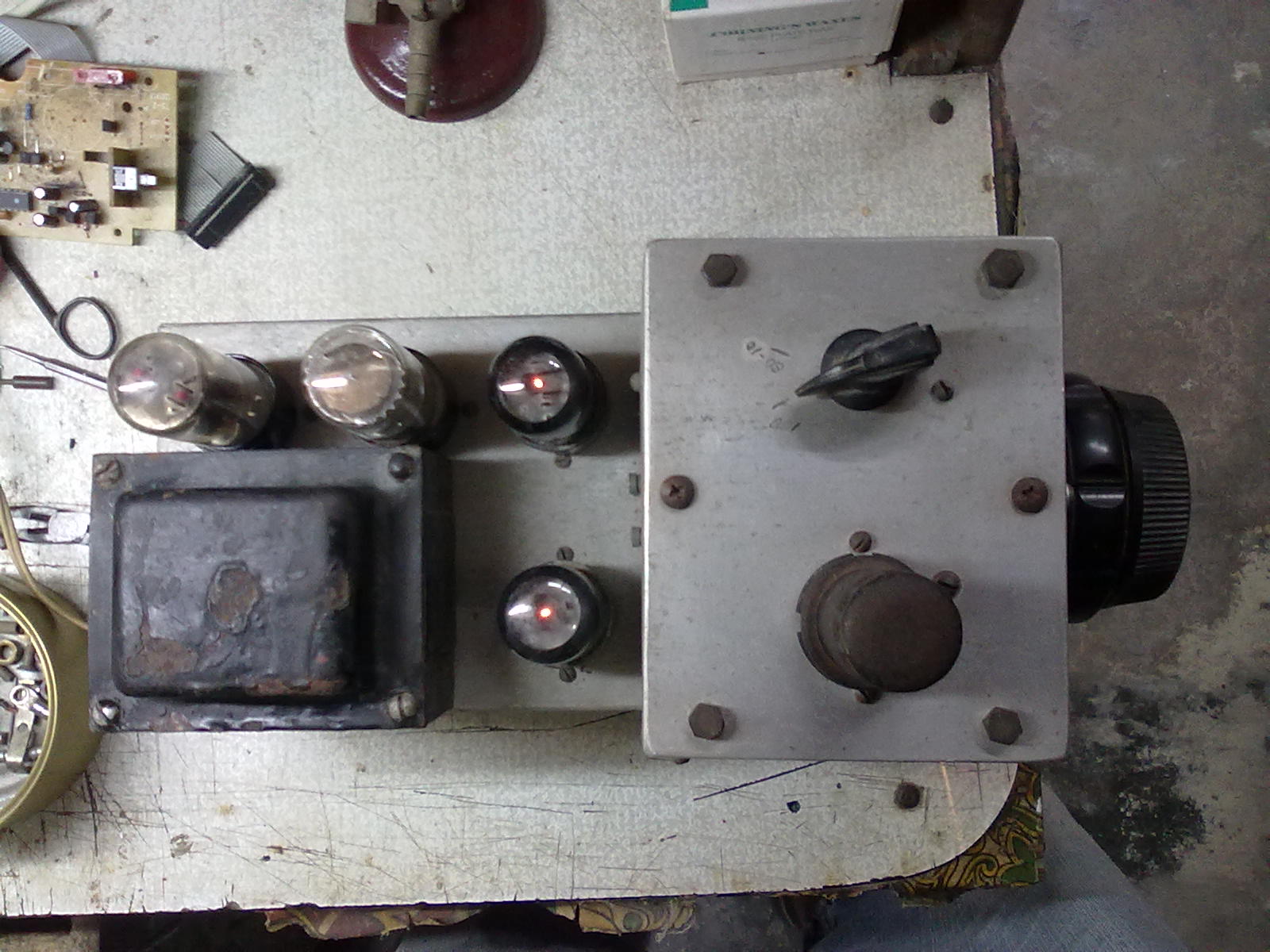
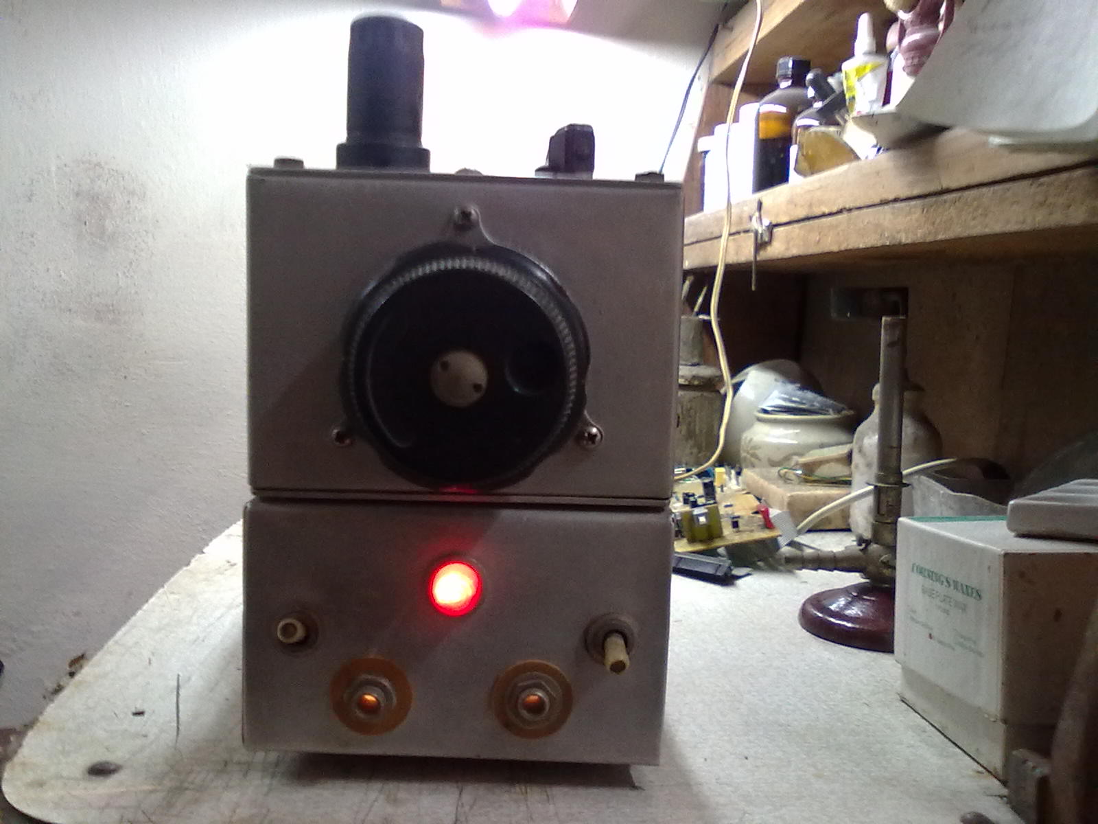
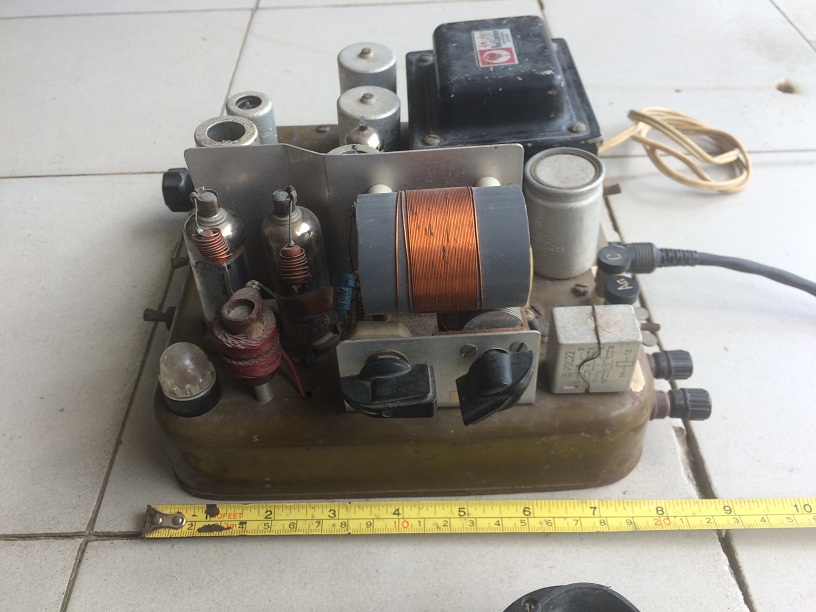
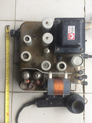
The VFO was also taken from a 1949 Handbook if I remember correctly, but I don’t have any literature on that, as you can see in the photo it has 5 5u4c rectifier valves, VR150 voltage stabilizer, 6v6 output, another 6v6 as a separator and a 6 )I(4 (60I94?) Soviet, in the oscillator. The stability they achieved in those years is incredible, I could communicate with stations that were on LSB and if I didn’t tell them that I was on AM they didn’t notice.
As a receiver I used an old Soviet AM and CW receiver, used by the Aviation HF stations of the 40s, which no longer exists hihihihihi
I’ll tell you how I tuned all that good ftuff: First I put the receiver in CW to beat the signal of the stations in SSB. After hearing them clearly, I removed the oscillator of the receiver and connected only the VFO of the Transmitter, and beat the signal with that of the receiver until I heard the other station clearly, then I put the transmitter to work and was ready to communicate.
There were many communications made with that station, even internationally on phone and CW.
Today everything is easier because with transceivers it is not necessary to go through all that work, but it is always good that those who did all this work know how radio was built and made.
73 Jose CO6EC
Obviously the transmitter
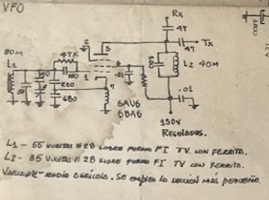
The two pictures above must be the VFO. It looks like the VFO in the 1947 ARRL Handbook.
I wonder what handbook this was? Spanish language.
I will be sending you some work of homebrew from the 80’s and 90’s when practically everything was manufactured by Cuban radio amateurs
The photos are of a Modulated Amplitude TX for the 160 Meter Band, about 25W of which several were made. The final tube was modulated in many cases by a 6DQ6, 2E26 or other similar ones that were very abundant at that time.
This one in particular ismade with valves6BH6 for the VFO, 6CL6 for the amplifier step and 6P23 Soviets in the final part, the modulator was made up of a 12Ax7 microphone preamplifier and a 6BM8 that came out through the cathode to the screen grid of the 6P23, in this way the carrier was controlled by modulation what we calledCarrier Controlas there was no voltage on the grid at the ends there was practically no carrierin the air which gave the impression of transmitting in SSB. hihihihihihi
For those who did not have a communications receiver, a conventional radio was adapted to receive that band, which in many cases was a VEF-206 of Soviet construction, to which an oscillator was adapted to beat the signal and get exactly on frequency. This was very popular here in the late 80’s and early 90’s.
Thanks Jose. We look forward to learning more about Cuban homebrew. The way in which radio amateurs got on the air with gear that they made themselves using the limited parts available to them is really interesting and admirable. 73 Bill
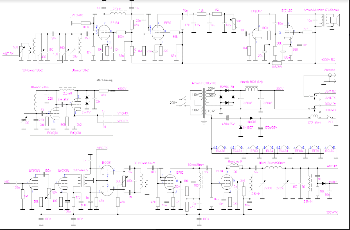
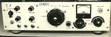
Jose CO6EC has been digging up 30 year-old Islander schematics for us. Thanks Jose. This one shows a VFO for the Islander. Note that it runs on 80 meters, but they select the second harmonic at 40 meters. This was a smart move that surely helped with VFO frequency stability.
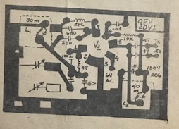
Jose sent this printed circuit board pattern for the VFO. Obviously they were making many of these rigs.
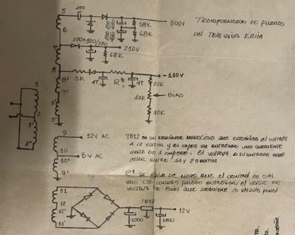
Here is the power supply. Jose reports that the transformer came out of a Soviet Krim 218 TV set. As a kid, I also pulled a transformer out of an old TV — I did it to build a power supply for a Heath HW-32A.
Here is another version of the Islander. Click on the image for a better view. Jose reports that this version was circulating during the time Islanders were being built. He says this diagram many have been done by Arnie Coro CO2KK (SK), and may have been circulated on the internet.
Here’s the first schematic that Jose sent. Again, click on the image for a better view.
I will continue to gather information on the Islander and the Jaguey. If you have any info please send it to me.
First a big congratulations to the Vienna Wireless Society and its President, Dean KK4DAS. In spite of low temperatures that made the Winterfest Hamfest live up to its name, this year’s ‘fest was a big success with excellent turnout both by buyers and sellers. There were a LOT of older rigs — on one table I saw three HT-37s. It was all great. Here is a video of the hamfest. https://www.youtube.com/watch?v=oheht5jCuKE&t=619sThis was shot early on Sunday morning March 19, 2023, about 30 minutes after it opened. An hour later there were a lot more customers.
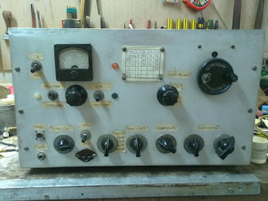
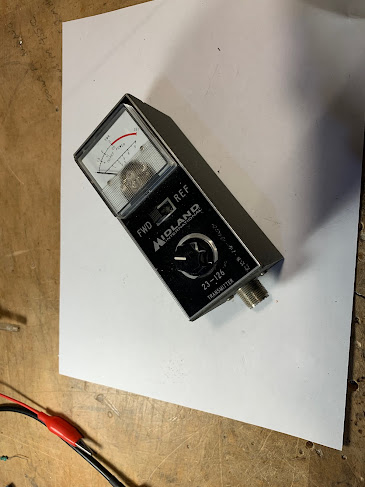
One of the first things I bought was the item pictured above. I bought it mostly because we are currently building 40 meter receivers with the local high-school students. I didn’t have a screw driver, so I couldn’t open up the box. Something was rattling around in there. I worried that the box might be mostly empty. Or that it would have one PC board with a sad collection of ICs. But in the hope that I would find something truly homebrew, I bought it.
Below are pictures of what I found inside. Can anyone tell us what this is? ( I recognized it immediately.) More on this device in due course.
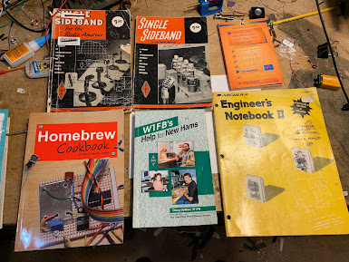
Other loot from the ‘fest:
The one on the left I’ve been using since around 1998! It is getting beat up. I bought the one on the right at the ‘fest. It is in much better condition. 5 bucks. TRGHS.
I always wanted one. I had nice leather case, but I gave it to Dick Dillman years ago. I now feel like a real boatanchor guy. I got for 15 bucks. I see on Amazon they are selling for $466!
I had one as a kid. Will be useful in the DR. In great shape.
Eamon Skelton’s book was a great find. As were the early editions of SSB for the Radio Amateur. Eight bucks for the whole lot.
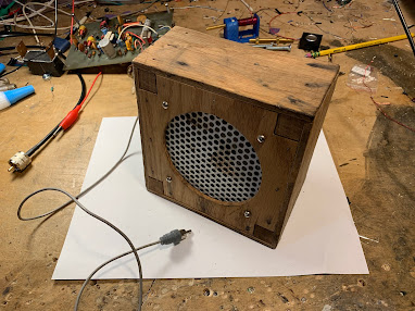
I like homebrew speaker enclosures. They add soul to the new machine. Perhaps a prize for the high-school project. Three bucks.
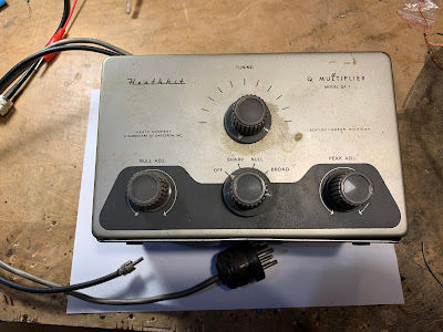
Finally, this thing. Plagued by guilt for past cannibalizations of QF-1s, I was going to pass on this one, but I realized that my friend Dean KK4DAS would be on his way, and if I didn’t take it (and extract the variable capacitor) he would. So I bought it. But I may leave this one as is, for possible use as the The Radio Gods intended. It could use some cleaning up. It seems to have a coat of nicotine. Ten bucks.
I also picked up a few larger knobs that may be of use with the high-school receivers.
This article, the pictures, and the comments are all so cool. They really capture the spirit of homebrew. Obviously we still need more information on the Islander and the Jaguey. If you have it, please send it to me and I will disseminate it via this blog.
I’ve been in touch by e-mail with Jose Campos CO6EC (the guy in the picture above). He sent me this partial schematic of the Islander (we still need the VFO circuit and the RF amplifier) . Thanks Jose!
Views: 2274
Comments: 6
Remembering
By José de Jesús Enríquez Campos (CO6EC)
Next 2019 will be the 30th anniversary of the first convention of radio amateurs in the province of Villa Clara, in Campismo de Ganuza, municipality of Corralillo, on the North coast, about 100 kilometers from Santa Clara, the provincial capital.
This convention was held on a national basis and colleagues from all the country’s provinces participated at that time. We did not reach a thousand members throughout the national territory and most of the radio amateurs worked in the 40-meter Band in Amplitude Modulation Then the Lateral Side Band (SSB) was the privilege of a few and the 2 meters was something rare, which did not yet exist in our environment.
At that meeting, a project for a Tube Transceiver was presented, quite simple, with just six vacuum tubes and a BF310 transistor. It was possible to work in HF in Double Sideband, achieving a greater efficiency than the transmission in Modulated Amplitude (AM). This project became known as the Islander.
In only two printed plates, one for the VFO and another for the TX and RX part, which by the way were printed for distribution, in a company in Villa Clara, due to their easy construction and acquisition of the components (almost all of them came out of a Krin-218 TV), a large number of such equipment were manufactured by radio amateurs from all over the country. Like everything made at home, it always comes up with a little problem that later is necessary with tinkering, correcting it.
I remember listening to an old radio amateur from Havana (whose callsign I don’t remember) in a pleasant QSO with another colleague, who jokingly said, “… some “Bugs” have now appeared in the band, called Islander, which is worse than the invasion of the Vikings…”, which gives an idea of how many were built at that time, when if you wanted to make radio, you had to manufacture it, something unusual in these times.
As soon as we saw the project we decided to build it, because at that time we had an AM “transmitter” with modulation by “Carrier control” with four tubes, a 12AX7 preamplifier; an ECL82, as a modulator, with cathode output to the final tube Screen grid, a 6DQ6 and a 6BH6 as VFO; and to receive, an old Russian receiver from World War II.
We got involved in the construction and improvements of the project and we managed, with some changes, to improve its performance and quality, because among the modifications to the original, we added:
-A switch, with which you could change the transmission mode to DSB -CW-AM. -A “Pi” Filter at the input of the RX, which considerably improved its quality. -An automatic volume control, because since it did not have AGC (Automatic Gain Control), when someone nearby came on, it would break your speaker. -A filter for the microphone input, which improved the quality of the modulation. -A final power stage, with a 6146B, with 750 V on the board, for about 70 W of output, taking advantage of the 6P15P as Driver. -The chassis was built from scratch using aluminum trays that were sold at the hardware store for “four pesos” each and that were special for making cabinets for these purposes.
After the construction was completed in one afternoon, with Reinaldo Martínez Domínguez (CO6UK), from Manicaragua, the balanced modulator was adjusted, since the good transmission of this type of equipment depends on the relationship between the amount of RF and audio that are mixed At that stage, it took us a long time to adjust, until Reinaldo with his expert ear told me, “leave it there, don’t touch it, it’s 99% complete”.
There were many international contacts that I was able to make with this very simple equipment, with very good reports, many of them with Europe, the American continent, that was very normal, since the propagation conditions in those years had nothing to do with the today, you could do half the world in AM, with about 100 W.
Many colleagues at that time asked me what equipment I was using. When I told them it was an Islander, they asked me to send them the plans of the improvements made, they were many modified plans, mimeographed.
Perhaps the youngest do not know what that was and the photos taken by colleague Joel (CO6JC) that helped to illustrate the distribution of the components in the chassis, were sent to radio amateurs from the different provinces, in the interest of contributing modestly to migrate from AM to the Double Side Band, today it is a rarity to listen to someone on AM, there are already few who appear in Double Side Band, which shows that we have developed in these almost 30 years, despite the difficulties, which We went from just under a thousand to about 8,000 throughout the country today.
From time to time, a colleague in the 40 meter Band, from another province, has told me that he still keeps the plans and photos that were sent to him at that time, or as “Kike” (CO6GO) that he still has a Islander as a relic.
Ours passed away a long time ago and part of its components went to other projects, thanks to Joel (CO6JC) there is a graphic record of it, and that at that time I had hair, which I have lost in these bustles.
With this brief comment, we only want the new generations to know what radio amateurs were like in those days and the older ones to remember it.
Nothing, to remember is to live again.
Here he left you some images.
(co6ec) Jose de Jesus Enriquez Campos
The first Image was the prototype presented at the Ganuza meeting, the rest of the photos were the ones we built with the improvements, and the photos and plans were sent to many colleagues, the colleagues who went to that meeting will remember, well, they still have to there are many left, because that was almost 30 years ago, greetings CO6EC
(co8zz) Raul Verdecie
Magnificent photographs!!!… They seem to have been taken today with some digital “super camera”!!! Really, from what I can see now, the CO6EC Islander was the perfect example… mine (my first radio and built by me) was also made like this, with the plates that the FRC sold and it was good, but very ugly …HI… The AGC worked wonderfully as it came, I don’t know if Jose’s improvements were later! With it I made my first hundred or so entities only in 40 meters / CW (between 7,100 and 7,150) when it was CL8ZZ. I gave it away so that someone would have their license and now I regret not having kept it… I would have liked to show it now to those who regret not having a radio!!!
(co8zz) Raul Verdecie
Ah, I can never forget those headphones!!!… my external hearing aids (read ears) are much smaller today thanks to them, they exerted tons of force on the operators’ skulls!!!
(cm6vml) Vidal
Very good article, I hope that one day, with a good teacher, I can build my own team, congratulations Jose, regards Vidal.
(co7wt) Pavel Milanes (CO7WT)
Sure…
My first radio and with which I got my CL7WT license back in the 90’s an ISLANDER, like that in capital letters.
I remember that the CL only had a small 40m segment (like now) and that it was full of broadcasts as soon as the afternoon fell, it was an odyssey to speak on the radio… you had to find a “little hole” between the Broadcastings where it wouldn’t bother you ” a lot” to be able to talk.
I remember that the old CO7OC (he is no longer a radio amateur) and CL7HU (now AC7HU) helped me build it with a board I bought at the radio club. I took almost all the valves from the deceased KRIM 218, then I found a store in Camagüey that sold idle things from the workshops…
Turns out they had such a large inventory of “idle” tubes that they couldn’t put it on the counter…they let me through to the warehouse…huge…stack of tubes, if I remember correctly I ended up with Chinese or Japanese tubes that they were more sensitive in the receiver… the driver went from a 6P14P to a more robust 6P9, by the end that was a humble 6P44 it became two 6P7s that were a Russian version of the RCA 607 if I remember correctly… in the end it had like 80W.
It goes without saying that when I said on the radio that there were valves in that place “they flew”….
The VFO was the one from the Jagüey, not the original from the Islander, I never knew about the AGC modifications.
I would like if someone has the plans with the modifications to send them to me, just for nostalgia…
My email pavelmc@gmail.com
(co2jc) Carlos Alberto Santamaría González
Brother, your article is very good, because of the nostalgia and also because it talks about what we radio amateurs like: tinkering. I didn’t have an Islander because what I started with in 2000 was a Polosa to which two colleagues helped me adapt it with VFO for 40 and 80 m. But I talked a lot with colleagues who did it with an Islander or a Jagüey and participated in the Rueda del Behique that I started in the 80 m. Others in the Hurricane Wheel that started a little later and were heard well. As you well say, the propagation at that time had nothing to do with what it is now, but it was very good to listen to the colleagues who came out with the equipment they had built. Thank you once again for your article. CO2JC
CO6CBF: “I began operating on the HF bands using homebrewed radios. Mainly on CW running just 10 Watts. My very first phone transmitter was a controlled carrier AM modulator for the 160m band using tubes and components salvaged from an old TV set.”
My good friend Dean KK4DAS has built a DSB rig for 10 meters and is working a lot of DX with it. Peter Marks in Australia has also jumped into the DSB game. A few of the students we are working with at the local high school may get their General Class licenses and convert their Direct Conversion receivers to Double Sideband transceivers.
All of this has caused me to reminisce about the famous Cuban Double Sideband rigs. Homebrew Hero Arnie Coro CO2KK used to talk about these rigs on his “DXers Unlimited” program on Radio Havana Cuba. But Arnie recently passed away, and with him I think a lot of the background info on the Cuban DSB rigs has also disappeared. I find very little about these rigs on the internet — I have not been able find a single picture. The Radio Havana Cuba archive of Arnie’s shows has disappeared.
Back in February I talked to Yulian CO6YI on 20 meters about the Cuban DSB rigs. He said he had a lot of background info on them, and said he would try to send it to me. I hope he is able to do this.
The results of my initial Googling appear below. There has to be more out there. I’m thinking that there must be a lot of background info on the Islander and Jaguey rigs sitting on the hard drives of radio amateurs. It is time to give this info wider circulation. Please send me any info you have on these rigs. Of particular interest would be schematic diagrams and photos of the rigs.
Date: Mon, 22 Mar 2004 17:48:59 -0500 From: "Prof. Arnaldo Coro Antich" Subject: Re: GB> 6EH7 vs. 6EJ7 as RF Amplifier
Dear amigo Chris: You are absolutely right ! EF184 is the best pentode for RF amplifier duty... But, let me ask you something... have you thought about the ECC88 and the even better ECC189 dual triodes that were designed for TV tuner work, and that incidentally were also about the last vacuum tubes ever designed from ""scratch"" until Phillips and other European manufacturers stopped from making receiving type vacuum tubes. The ECC189 is simply wonderful for a front end !!! I am sure that you are aware of our limitations here at my QTH regarding the possibility of obtaining solid state modern devices... so we still make ""new"" ham radio rigs using mostly vacuum tubes... We even still make a version of "" The Islander"" a DSB transceiver with direct conversion vacuum tube receiver... Tube lineup is EF184 RF amp ECH81 product detector ECH81 triode section not used ECL82 triode audio preamp ECL82 pentode audio output 6AH6 VFO ( Russian equivalent 6*5P ) Audio filter provided by good working brain of operator !!! Keep up the good work amigo !!! 73 and DX YOur friend in Havana Arnie Coro
Today’s first question came from a long time listener in India. Rajiv tells me that at this moment he is not able to pick up our station on the shortwave bands, and he rightly assumes that this is because of the very low solar activity… but Rajiv who lives in the garden city of India, Bangalore, the home of the nation’s electronic and other high tech industries, is able to read the scripts of the program that are made available to several short wave listeners clubs e-mail distribution lists. Rajiv tells me that he wants to obtain the electronic files of the Super Islander amateur radio transceiver to compare the circuit diagrams and design philosophy with a similar project that is becoming very popular among Indian radio amateurs. Ok amigo Rajiv… I have already sent you all the files including some nice digital photos of the first prototype of the Super Islander, that as you will see, has two final amplifier options , one built using NPN RF power transistors, and the other one using two vacuum tubes that are very easy to find here in Cuba from recycled TV sets. The Super Islander is a single band transceiver that can be built for the 160, 80 or 40 meter bands. Here in Cuba amigo Rajiv, the most popular amateur band nowadays is two meters, using the FM narrowband mode, and the second most popular band among Cuban radio amateurs is 40 meters, that’s why most of the Super Islanders are built for operating between 7.000 and 7.150 kiloHertz. The double sideband signal generated by the Super Islander simple circuit is very stable, and very few if any radio amateurs that contact stations using the Super Islander are able to detect that it is a double side band and not a single side band signal what they are hearing. One of the most outstanding features of the Super Islander single band amateur radio transceiver is that it is modular, so those who want to build it, are able to build and test each module as a single project, and after all the modules are fully tested, then they are easily wired together . The parts count, that is the number of components required to build a Super Islander was kept intentionally as low as possible, both to simplify its construction and to increase the reliability. I hope that amigo Rajiv in Bangolore , India will be able to make good use of the Super Islander’s files, and maybe even go ahead and build one , as the parts required are almost universally available, because that was one of the design requirements that I set when starting the Super Islander project more than fifteen years ago….You can learn more about this simple amateur band transceiver by sending a request for the Super Islander files to arnie@xxxxxx … I will send it as a dot zip file and you will be able to see circuit diagrams, photos and full descriptions of the different modules of this nice little rig, that has proven itself under the most difficult circumstances, like handling emergency communications links during tropical storms.
Beginners generally build one of two radios; the vacuum tube Islander or the solid state Jaguey. The Islander is a DSB/CW Cuban design using a very clever low parts count circuit and a direct conversion receiver. The Jaguey, named for the Jaguey Grande Radio Club in Matanzas province, is a generic design, with a DC receiver, DSB and CW, using solid-state components. Many of its ideas are from Wes Hayward's W7ZOI's Solid State Design for the Radio Amateur. The lack of mechanical filters or quartz crystals to homebrew SSB filters made Cuban designers CO5GV, CO2JA and CO2KK choose a DSB and CW rig. Fitted with good quality capacitors for the VFO, it works quite well from a 12-volt car battery in hurricane emergencies.
Don’t let the scary nuclear chemistry title put you off — there is a LOT of very familiar homebrew stuff in this video. You will feel right at home. Many of the resonances take place in the ham bands. The CBLA may have to get involved here.
Thanks to Chuck WB9KZY for sending this.
And check out Ben’s video on is best projects from the last 10 years:
This is really cool. Pete Juliano N6QW is interviewed by his daughter Gina. (You can hear it by clicking on the link above.) Gina has a podcast about the music industry called Mission to Music. I liked it a lot. I never realized that Pete was such big fan of rock music. I was especially touched by Pete’s closing comments on his words to live by: “Always tell the truth and do the right thing.” Words to live by indeed. Thanks Pete. And thanks Gina!
For the capacitive element in the LC circuit we have essentially two 660 pF caps in series.This results in a total capacitance of 330 pf.I measured 362 pF.
To get a resonant frequency of 7.0 MHz with 362 pF we need 1.428 uH.
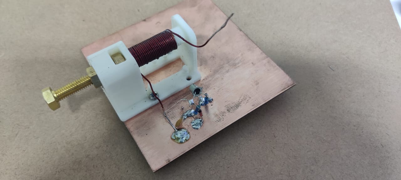
To get 1.428 uH on the PTO coil form we need about 21 turns of wire.
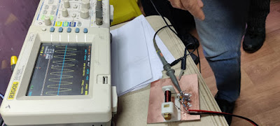
21 turns on our coil form yields 1.440 uH and resonates with 362 pf at 6.9708 MHz
That’s pretty close to what we need, but the problem arises when we screw in the brass tuning screw. This reduces the inductance and raises the frequency. Putting the screw all the way in reduces the inductance to 1.138 uH resulting in a resonant frequency of 7.8414 MHz.So with a coil this large (that we must use if we want to tune down to 7.0 MHz) we end up with a tuning range that is far too large.We only need 7.0 to 7.3.In effect, this means that we end up using only a small portion of the tuning range:We can turn the screw approximately 34 times, but only 6 turns keep us within the range of 7 to 7.3 MHz (the 40 meter band).There is about 50 kHz per turn of the dial.This makes tuning difficult.It becomes more difficult to separate stations and tune them in.It would be better if we could tune across the band using more turns of the dial.At least 15 turns of the dial would be nice:That would mean about 20 kHz per turn.But how can we do this?
Possible solution #1:Steel screw with tighter pitch on the turns.
Just using a steel screw slows the tuning rate down.In a normal PTO we increase the inductance (and reduce the frequency) by gradually introducing a ferrous material that increases the inductance of the coil, pushing the frequency of oscillation down.But our brass screw is non-ferrous.This means that putting it into the core does not change the permeability of the coil.The permeability of brass is the same as that of air.
What does happen, however, is that introducing the brass screw into the coil causes currents to flow in the screw.These are called eddy currents. In effect they become shorted secondary coils. And they have the effect of lowering the inductance of the coil – this is why the frequency of the oscillator increases as we screw in the brass screw.
When you use a steel screw you get both effects: As you screw it in, eddy currents flow in the screw, reducing the inductance and increasing the frequency of oscillation.But you are also introducing ferrous material – this pushes in the opposite direction, increasing induction and lowering the frequency of oscillation.I think the eddy current effect dominates, but the increase in permeability pushes in the opposite direction.This means that with a steel screw you have to use more turns to cover the same frequency range. And that is what we want.
But there is more:steel screws are also available with tighter (#28) thread pitches. The Hillman 45479 uses this tighter thread pitch. This too means that more turns are needed to move through the same tuning range. Again, that is what we want.
I found that using a steel screw with #28 thread pitch allowed for the coverage of the 40 meter band in approximately 11 turns of the dial.That is much better than what we got with the brass screw:About 27 kHz per turn instead of the 50 kHz per turn that we got with brass. But it is not quite good enough.It would be better if we could use the entire range of that PTO coil form.
Solution Two:Add a fixed inductor in series with the PTO coil.
After some noodling, I decided to split up the inductor:A portion of it would remain fixed, the other portion would continue to be tunable.
I estimated that I was starting out with a coil of about 1.428 uH.So I just put a 1 uH choke in series with the variable inductor and reduced the variable coil to about .428 uH (about 9 coil turns).This worked, but it worked a bit too well!It would not tune the entire 40 meter band.So I figured I needed less fixed inductance and more variable inductance.I found an air-cored coil in my junk box and cut it so that it measured about .650 uH.I added turns to the variable coil, going to a total of 15 turns.This REALLY worked well and yielded the 26 or 27 turns to tune across 40 meters that you can see in the video.
TWEAKS:
Later, I tweaked it a bit more: With 15 turns of #22 wire on the variable inductor, a steel screw tuned from .791 uH (screw out) to .662 uH (screw in). I put one additional turn on the fixed inductor, making it .749 uH, or about 8 turns of #22 (wound tighter on a cardboard tube from a coat hanger than was the coil on the variable inductor). With these coils I could tune from 6.9772 to 7.386 MHz. That’s a bit more than we need but this allows us to keep the tuning away from the ends of the coil where tuning is more likely to become non-linear. I am able to go from 7.0 to 7.3 MHz in 23 turns of the dial. And the tuning is quite linear: The first turn from 7.0 MHz moves the frequency 12 kHz. At the mid-point of 7.150 MHz, one turn of the dial moves the frequency 12 kHz. At the high end, going down from 7.3 MHz, one turn of the dial moved the frequency 11 kHz. That, for me, is VERY linear tuning. You probably will have to adjust the coils a bit (just squeezing the turns together or spreading them apart) to get the tuning range where you want it.
YMMV – Keep it simple!
Like they used to say in the commercials:Your Mileage May Vary. There are many ways of doing this.The objective is smooth tuning across the 40 meter band.I think that by varying the pitch of the variable coil turns you could get a more linear tuning response (please let us know if you have any luck).You might also be able to get similar results by changing the amount of capacitance in the feedback network (which is also the frequency determining element in this simple Colpitts oscillator).But remember that simplicity and a low parts count were also our objectives in this.This mod adds only 1 part (the fixed inductor), requires the removal of some turns from the main tuning cap, and perhaps the replacement of the brass screw with a steel #28 screw and nuts.
We might present to the student this problem and our search for a solution. This would be a good example of how homebrewers work to make their rigs better and easier to use. It illustrates well the design dilemmas that can come up, and how amateurs like us can come up with solutions.
This is a really great video on how Mr. Carlson (VE7ZWZ) did troubleshooting on a tube-type receiver. The problem was an intermittent. They can drive you nuts, but Mr. Carlson show us how to stay sane.
— His use of ordinary observation at the start of the process is very important. He notices a flickering glow in the voltage regulator tube. The flickering coincides with the intermittent noise that he is trying to fix. That is an important clue.
— He also can see that the grid of one of the AF amplifier tubes is getting way too hot: grid emission. That is another important clue.
— He checks the grid voltage on the AF amplifier and finds that it is way too low. It is fine on the other side of the resistor that carries the voltage to the tube. But it is close to zero at the grid. This means that the mica capacitors on the grid are suspect.
— He uses some fairly esoteric test gear — a homemade device and an an old Heathkit signal tester — to check his diagnosis. They confirm that the mica caps are the problem. He replaces the caps and the problem is gone. A very satisfying troubleshoot.
Mr. Carlson presents us with a lot of good info:
— 6K6 tubes were often in fact 6V6 tubes. And 12AX7s were often 6VJ8s! Manufacturers were deliberately re-branding tubes. So we shouldn’t be surprised if some of our solid state devices turn out to be a bit different from what was promised. This practice goes way back.
— I liked Mr. Carlson’s final sensitivity test on the receiver — he just waved his hand near the antenna connection and we could hear the receiver respond. Excellent.
— Mr. Carlson is very negative about the use of polystyrene caps in oscillator circuits. But we these simple and cheap caps being used to good effect in oscillators in India.
— The leaky and bad micas were a bit surprising. Carlson speculates that their proximity to heat-producing resistors might have caused the trouble.
Finally, it is interesting to hear the Canadian pronunciation of radio words: Solder with the L pronounced (as in the UK). Farad with the second A long and the final D emphasized (I say it just as the first two syllables of Michael Faraday’s last name).
HE’S BACK! HOORAY! PETE JULIANO N6QW IS BACK! SOLDERSMOKE COMMUNITY WAS SENT INTO A COLLECTIVE FUNK BY PETE’S ABSENCE.—————-Pete’s TR-7 (SEE VIDEO ABOVE)CK722The BFR106
Pete’s new blog: https://hamradiogenius.blogspot.com/—-Update on the high school project: Mixers made. Harder than they seemed.First QSO with the DC RX. Allan W4AMV Homebrewer TRGHSTen Minute Transmitter – Better than the MMM! AF4K (SK) crystals.Other supporting projects: Farhan in Hyderabad. Rick N3FJZ, Walter KA4KXX, Andreas DL1AJG Electronics for Biologists. Peter Marks VK3TPM (fighting the siren call of the Si5351) . Steven VK2BLQ built a beautiful one. Daniel VE5DLD will build three of them with his students. Orlando PY2ANE is building one in Brazil.This week: The Bandpass Filter. (Thank you Hans Summers)—SHAMELESS COMMERCE DIVISION:BECOME A PATRON VIA PATREON. I am posting some fun stuff for the Patrons.AMAZON SHOPPING ADS Now on both the left and right columns.CHECK OUT Mostly DIY RF in the right hand column.—-My HP8640B Lives to Fight another day. Two new DMMs A low-end Fluke and a AstroAI 6000Electrolytic Replacement Controversy Continues
Mailbag: — Dave AA7EE is blogging again! Yea!— Mike Rainey AA1TJ back in the Hobbit Hole Building a WWVB receiver.— Farhan is coming to FDIM.— Tony G4WIF reminds us that 39 bucks for JUST a 60 MHz counter would be great!— Dave VE3EAC again helped me fix my HP8640B.— Dean KK4DAS finalizing 10 meter DSB rig. FB. Upgraded my NanoVNA.— Mike KD4MM giving me a Nano VNA for the SolderSmoke Shack South.— Ian VK3LA asked what happened to Chuck Adams content. Good question.— Don ND6T and I have been discussing envelope detection.— Nick M0NTV working on AM modulators. He has a new video.— Ciprian YO6DXE built a Ten Minute Transmitter.— Steve EI5DD Connacht Regional News: https://www.docdroid.net/YJAV800/crnews0223-pdf
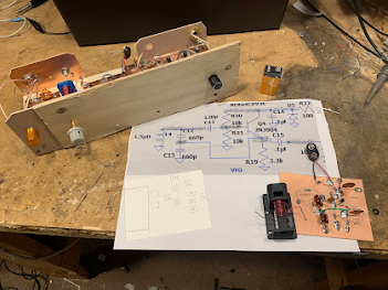
Farhan came up with the idea of having high school students build their own receivers. We followed his lead — there are now several such projects underway around the world.
The simple but effective Colpitts circuit that Farhan recommended.
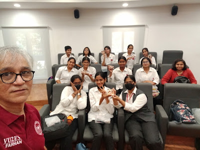
Farhan sent this picture yesterday. If you look closely you can see the students holding their homebrew 40 meter Direct Conversion receivers. You can even see that they are using the same kind of PTO coil forms that we are using here. Farhan reports that 11 receivers were built by 33 students. A few more are being finished and will soon be active in Hyderabad.
I was really blown away by this picture. We are doing the same things on different sides of the world. Our students will like this. It will be as if they are seeing people of the same age building the same receivers 7,500 miles away.
In our last session I mentioned to our students that Farhan of Hyderabad had given us the toroidal transformers that they are putting into their mixers. I told them that in ham radio, when we use parts given to us by a friend we add “soul to the new machine.” And I said that Farhan would be coming to see them in May. They were really impressed.
We are starting to see similar efforts in different parts of the world — Andreas with university students in Germany, Daniel with high school kids in Canada. We hope there will be others.
I’d really come to like this old signal generator. The construction is superb. It was built to be repaired. As you open it up you find all kinds of useful diagrams and pointers. It is very solidly built – it looks like something that was built for the Apollo program. And it was given to me by a friend: Steve Silverman KB3SII gave it to me in 2017 — he had it in his New York City shack. Dave Bamford W2DAB picked it up for me just before Steve moved out of the city.
I’ve already done one complex repair on it — one of the tines on one of the selection switches fell of and I had to replace the tine. That was difficult, but it was a very satisfying repair.
But lately, the HP8640B started acting up again. It developed an intermittent problem that caused both the signal generator and the frequency counter to just shut down.
I was thinking that this might be the end of the road for the HP8640B. I even started looking for alternatives. But they were all very unappealing. They come in plastic boxes with names like Feeltech and Kooletron. The boxes are filled with flaky wiring and boards hot glued to the plastic. Yuck. The contrast with the HP8640B could not be stronger.
So I started to think about the problem. This was the first part of the troubleshooting process. I asked myself: What would cause several different systems (counter, frequency generator, and display) to all shut down? The power supply was a leading candidate.
I started reading the power supply section of the HP8640B manual. There was a line in there that caught my eye: The power supply boards had on them LEDs that glowed if the board was functioning. Thank you Hewlett Packard! I opened the top of the signal generator and found the power supply boards. Sure enough, there were the LEDs. I turned the generator on, and found that one of the lights was out. Bingo. (Trevor takes a look at the power supply boards in the video above. I have it cued up to the 12:57 point at which he talks about and shows these boards.)
Here was the other clue: The problem was intermittent. It kind of seemed like a loose connection. So I just unseated the board and took it out. I put some De-Oxit on the connector and popped it back in. Boom: The LED came on and the HP8640B came pack to life.
There is a whole bunch of great info and videos on the HP8640B on the internet. It is almost as if a cult has developed. This signal generator is worthy of a cult following. Count me in.
I especially liked the video below. Kevin really captures the admiration that many of us feel toward the way this piece of gear was built. He also kind of hints at the way this sig gen could become a pirate transmitter on the FM broadcast band (at 8:44):
I know that eventually the problematic plastic gears in this device might fall apart. I am prepared for this: I already have the metal replacement gears from India.
Thanks again to Steve Silverman KB3SII and Dave Bamford W2DAB for bringing me into the HP8640B cult.


(co6ec) Jose de Jesus Enriquez Campos
The first Image was the prototype presented at the Ganuza meeting, the rest of the photos were the ones we built with the improvements, and the photos and plans were sent to many colleagues, the colleagues who went to that meeting will remember, well, they still have to there are many left, because that was almost 30 years ago,
greetings CO6EC
(co8zz) Raul Verdecie
Magnificent photographs!!!… They seem to have been taken today with some digital “super camera”!!!
Really, from what I can see now, the CO6EC Islander was the perfect example… mine (my first radio and built by me) was also made like this, with the plates that the FRC sold and it was good, but very ugly …HI… The AGC worked wonderfully as it came, I don’t know if Jose’s improvements were later! With it I made my first hundred or so entities only in 40 meters / CW (between 7,100 and 7,150) when it was CL8ZZ. I gave it away so that someone would have their license and now I regret not having kept it… I would have liked to show it now to those who regret not having a radio!!!
(co8zz) Raul Verdecie
Ah, I can never forget those headphones!!!… my external hearing aids (read ears) are much smaller today thanks to them, they exerted tons of force on the operators’ skulls!!!
(cm6vml) Vidal
Very good article, I hope that one day, with a good teacher, I can build my own team, congratulations Jose, regards Vidal.
(co7wt) Pavel Milanes (CO7WT)
Sure…
My first radio and with which I got my CL7WT license back in the 90’s an ISLANDER, like that in capital letters.
I remember that the CL only had a small 40m segment (like now) and that it was full of broadcasts as soon as the afternoon fell, it was an odyssey to speak on the radio… you had to find a “little hole” between the Broadcastings where it wouldn’t bother you ” a lot” to be able to talk.
I remember that the old CO7OC (he is no longer a radio amateur) and CL7HU (now AC7HU) helped me build it with a board I bought at the radio club. I took almost all the valves from the deceased KRIM 218, then I found a store in Camagüey that sold idle things from the workshops…
Turns out they had such a large inventory of “idle” tubes that they couldn’t put it on the counter…they let me through to the warehouse…huge…stack of tubes, if I remember correctly I ended up with Chinese or Japanese tubes that they were more sensitive in the receiver… the driver went from a 6P14P to a more robust 6P9, by the end that was a humble 6P44 it became two 6P7s that were a Russian version of the RCA 607 if I remember correctly… in the end it had like 80W.
It goes without saying that when I said on the radio that there were valves in that place “they flew”….
The VFO was the one from the Jagüey, not the original from the Islander, I never knew about the AGC modifications.
I would like if someone has the plans with the modifications to send them to me, just for nostalgia…
My email pavelmc@gmail.com
(co2jc) Carlos Alberto Santamaría González
Brother, your article is very good, because of the nostalgia and also because it talks about what we radio amateurs like: tinkering. I didn’t have an Islander because what I started with in 2000 was a Polosa to which two colleagues helped me adapt it with VFO for 40 and 80 m. But I talked a lot with colleagues who did it with an Islander or a Jagüey and participated in the Rueda del Behique that I started in the 80 m. Others in the Hurricane Wheel that started a little later and were heard well. As you well say, the propagation at that time had nothing to do with what it is now, but it was very good to listen to the colleagues who came out with the equipment they had built. Thank you once again for your article. CO2JC