Polyakov (RA3AAE) Direct Conversion Receiver: 40 meter DC RX with VFO at 3.5 – 3.6 MHz (with video)

I’ve been reading about Polyakov (or “sub-harmonic”) Detectors for a long time:

https://soldersmoke.blogspot.com/search/label/Polyakov–Vladimir

But until now, I never built one. Recently, Dean KK4DAS and the Vienna Wireless Makers group have been building a Direct Conversion receiver. Their receiver uses an Si5351 as the VFO, but of course Dean and I have decided to try to do things the hard way by building non-digital VFOs. At first we just came to the conclusion that my earlier Ceramic Resonator VFO wasn’t much good (it drifted too much). This led us into standard Colpitts and Armstrong VFOs, and the fascinating world of temperature compensation. Then I remembered the Polyakov circuit — this would allow us to use a 3.5 MHz VFO on the 7 MHz band. Lower frequency VFOs are easier to stabilize, so I started building my first Polyakov receiver. You can see the results (on 40 meters) in the video above.

I started working with a circuit from SPRAT 110 (Spring 2002). Rudi Burse DK2RS built a Polyakov receiver for 80 and 40 that he called the Lauser Plus. (Lauser means “young rascal” or “imp” in German.) For the AF amplifier, I just attached one of those cheap LM386 boards that you can get on the internet. With it, I sometimes use some old Iphone headphones, or an amplified computer speaker.

The Polyakov mixer is a “switching mixer.” The book excerpt below shows how I understand these circuits. The enlightenment came from the Summer 1999 issue of SPRAT (click on the excerpt for an easier read):

Leon’s circuit shows us how a simple switching circuit in which the switches are controlled by the VFO can result in an output that has the sum and difference components. That is the hallmark (and most useful part) of real mixing. Remember — we say that mixing happens in non-linear circuits when the passage of one signal depends on what is happening with the other signal. A switch is as non-linear as you can get! And that switch is being controlled by the VFO.


In a Direct Conversion receiver we usually run the VFO at the operating frequency. This results in audio just above and just below the operating frequency.

The Polyakov Direct Conversion circuit is a bit different. It has the switches (the diodes) turned on twice each cycle: When the VFO voltage goes to a positive peak, this turns on one of the diodes. When the VFO goes to a negative peak, this turns on the other diode. So in effect the switch is being turned on TWICE each cycle. So with the Polyakov you run the VFO at HALF the operating frequency. For a DC receiver designed to run around 7.060 MHz, you build a VFO at around 3.53 MHz. This has some immediate advantages. My favorite is that it is easier to get a VFO stable at a lower frequency. It is easier to stabilize a VFO at 3.53 MHz than it is at 7.060 MHz.

When you open that SW 1 switch in the Lauser Plus, you no longer have a Polyakov mixer. Now you just have a diode mixer. It will be opening and closing once each cycle at the VFO frequency. DK2RS used this to cover not only the 40 meter band (in Polyakov mode) but also the 80 meter band (in single diode detector mode). That is why DK2RS has that big variable capacitor in the input circuit — that LC circuit needs to tune all the way down to 3.5 MHz and all the way up to around 7.3 MHz. (I used a coil of about 6.5 uH to do this.)

With just one diode and operating at 80 meters, it works, but not as well as it does in the Polyakov mode on 40. I can pick up 80 meter signals, but in this mode there seems to be more of an “AM breakthrough” problem. “Experimental Methods in RF Design” on page 8.11 describes what is going on (the last sentence is most relevant here):

Here are some very good links with information on the Polyakov receiver:

LA8AK SK: http://www.agder.net/la8ak/ Almost seventeen years after his death he continues to help his fellow radio amateurs through his web sites. TNX OM! FB!
I will post a video tomorrow showing the receiver in operation on 80 meters.

Three cheers for Vlad Polyakov, RA3AAE

Model Rocket Lands Like a SpaceX Falcon 9

I had a blog post about this in 2018:

https://soldersmoke.blogspot.com/2018/06/rockets-and-microcontroller-videos.html

He has finally achieved the very difficult goal of landing his model rocket just as SpaceX does with its Falcon 9. Check out the video above.

It was also very cool to see him building the rocket, using a very wide range of electronic, software and metalwork skills.

Hack-A-Day has a good post explaining how he did this:

https://hackaday.com/2022/08/05/bps-space-succesfully-lands-a-model-rocket/

Congratulations to BPS.space!

SolderSmoke Podcast #239: Hex DX, VFO Temp Comp, DC RX, Polyakov!, DX-100, Wireless Set, Farhan’s “Daylight Again” HDR rig, MAILBAG

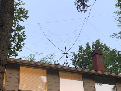
N2CQR Hex Beam Aimed at Europe


SolderSmoke #239 is available for download:

http://soldersmoke.com/soldersmoke239.mp3

TRAVELOGUE:

James Webb Space Telescope. Mars returning to opposition in early December.
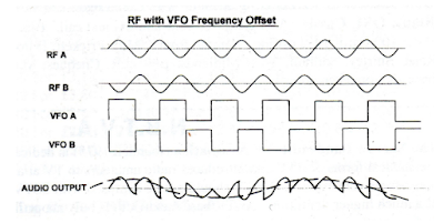
BILL’S BENCH

Hex Beam K4KIO – on roof – TV Rotor – 20-17-12 Lots of fun. Working Japan regularly, Australia, South Africa on long path 17,000 miles. 52 countries SSB since July 11.

VFOs and Temp stabilization. Dean KK4DAS found my ceramic resonator VFO for DC receiver drifty. He was right. So I built a real LC Colpitts VFO. Got me into temp stabilization. A new hobby! An obsession. HT-37 and Ht-32 parts. Ovens? WU2D’s second VFO video. Understanding thermal drift and how to address it. Split stator caps. Cut and try.

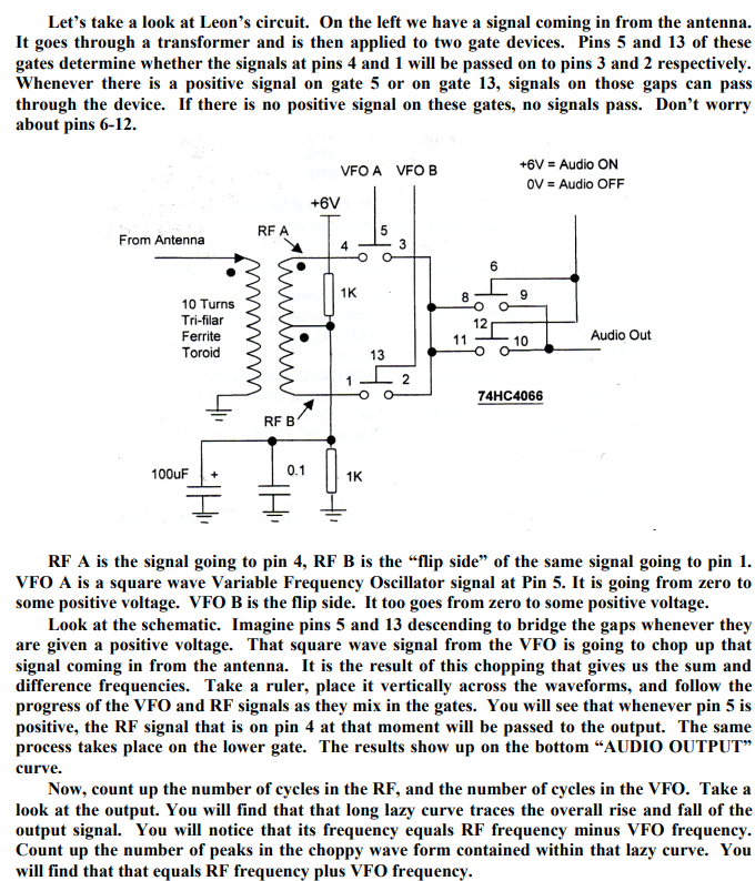
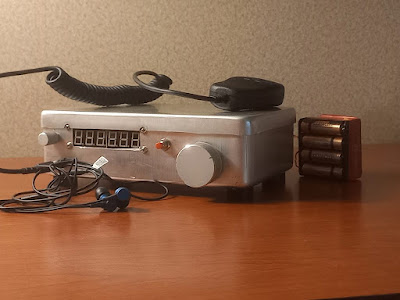
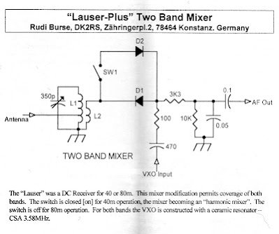
Built a Polyakov DC Receiver. https://soldersmoke.blogspot.com/2010/03/polyakov-plus-dual-band-receiver-with.html Lauser Plus. Lauser = Imp or Young Rascal! DK2RS. He used a ceramic Resonator VXO at 3.58 MHz. Mine works great on 40 with VFO running 3.5 — 3.65 MHz. See schematic below.

On 40 AM with DX-100 and MMMRX. DX-100 died. 12BY7 VFO buffer went bad. How common is failure in this tube type? Nice QSO with Tim WA1HLR about the DX-100.

Got my Dominican license: HI7/N2CQR! SSSS on the way. Thanks to Radio Club Dominicano and INDOTEL.

Getting more active in the Vienna Wireless Society.

BOOK REVIEW:

“The History of the Universe in 21 Stars” by Giles Sparrow. Written during the pandemic. Published by Welbeck, in London. https://www.amazon.com/History-Universe-21-Stars-imposters/dp/1787394654 Also: From “Atoms to Amperes” by F.A. Wilson available for download. See blog.

SHAMELESS COMMERCE DIVISION:

Todd K7TFC getting ready to launch “Mostly DIY RF.” I used his TIA boards in my 1712 rig. He will have boards like this and much more. Stay tuned.

I need more viewers on YouTube. They want 4,000 hours IN A CALENDAR YEAR! Please watch!

FARHAN’S NEW “DAYLIGHT AGAIN” RIG. Analog. VFO. Comments, observations. We need to get him on the podcast. Maybe two shows: SDR and HDR.

PETE’S BENCH

Time very limited. But still sharing lots of tribal wisdom.

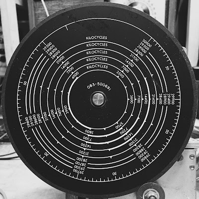
Wireless set with tubes!

Tool recommendation – Air compressor

MAILBAG:

Farhan VU2ESE – Speaking of big antennas “Whenever I look at the huge construction cranes in Hyderabad, I always think how one could make 160m, 4 element yagi using it as a boom..

Todd K7TFC in Spain, spotting Log Periodics in Madrid.

Andreas DL1AJG: Can Biologists fix Radios?

Janis AB2RA Wireless Girl. Expert on Hammarlunds. And was my first contact with the Tuna Tin 2. She too was HB!

Peter Parker VK3YE on Owen Duffy VK1OD

Lex PH2LB on homebrew radio

Would this really be homebrew? Mail from H-A-D article on FM receiver

F4IET a DSB rig from France

Ciprian got his ticket YO6DXE

Josh G3MOT sent us a good video about the Vanguard satellite and IGY.

Dave Wilcox K8WPE bought Chuck Penson’s Heathkit book.

Rogier — So many great articles and links from PA1ZZ

Bill AH6FC Aloha. Retiring. Wants to build. Mahalo!

Grayson KJ7UM Working on an Si5351. Gasp.

Mike KE0TPE viewing YouTube while monitoring 6 meters. He will have a lot of time to watch!

Chris KD4PBJ spotted Don KM4UDX from VWS FB

Mark WB8YMV building a superhet. Having trouble with 455 kc IF can filter.

Walter KA4KXX Great comment on the Daylight Again rig.

Ramakrishnan Now VU2JXN was VU3RDD. Found lost Kindle with SolderSmoke book on it. Building SDR rig from junk box. Trouble with the LM386.

Pete, Farhan and Tony: Shelves of Shame

Daylight Again by Farhan
The Polyakov receiver I built yesterday (from SPRAT 110, 2002!)

Farhan Takes us Back into the Daylight — An Analog Rig with a Homebrew Crystal Filter and an LC VFO

There is so much radio goodness in this rig and in the blog post that describes it. Farhan’s blog post will keep us busy for a long time. There is much to learn there. But perhaps even more important is his larger view of the role of analog circuitry in ham radio. Here are a couple of excerpts from his introduction:

Here is the memo : The analog never died. The world is analog all the way, until you descend into Quantum madness. The antennas are analog, Maxwell died a content, analog man. Our radios, ultimately, are analog machines and we are all analog beasts too. Amateur Radio technology has evolved into the digital domain. However, it has only made it easier for us to do analog with computers to simulate and print our circuits. So, it’s time to bid good bye to our Arduinos and Raspberry Pis and build an Analog Radio for ourselves. So let’s see what we can achieve in hindsight, a return to our native land and a rethink of our approaches. The radio is called Daylight Again, a nod to being back at the FDIM in 2022 after a gap of two years. It is named after the Crosby, Stills, Nash and Young’s song that had been humming all the time while put this radio together, emerging after 2 years of lockdown. This radio that took two days to come together, no actually two years! That’s: parts of it got built and stowed away, thoughts were struck in the shower, questions popped up during early morning cycle rides and notes and circuits were scribbled in the notebook. I must take the first of many diversion here: I hope you all maintain a notebook. Write down the date and whatever you thought or did on the bench and the result. Nothing is trivial enough to leave out. Wisdom comes to those who write notes. I started to build this on Saturday the 14th May and I checked into the local SSB net on Monday morning, the 16th May 2022.

AND

Having clean VFO is the most important way of increasing the dynamic range of your radio. A free running JEFT VFO that has sufficient power and a good Q components, will be unmatched by any synthesized or direct sampling radios. The math is all on the side of the free running VFO. We are talking -150 db/Hz at 10 KHz spacing, by comparison the Si5351 is -125 db/Hz, it is 300 times worse.

That is just part of the intro. We should all study the rest of Farhan’s blog post very carefully and incorporate the wisdom into our new rigs:

Here is the blog site:


Enough of the darkness. Step into the daylight my friends.

Can a Biologist Fix a Radio?

Andreas DL1AJG (who in real life is a professional biologist) sends us this excellent article about how biologists approach problems in living cells as opposed to how engineers or technicians approach problems in broken radios.

This excerpt from the 2002 article gives you an idea of the tone and content of the article:

“… I started to contemplate how biologists would determine why my radio does not work and how they would attempt to repair it. Because a majority of biologists pay little attention to physics, I had to assume that all we would know about the radio is that it is a box that is supposed to play music. How would we begin? First, we would secure funds to obtain a large supply of identical functioning radios in order to dissect and compare them to the one that is broken. We would eventually find how to open the radios and will find objects of various shape, color, and size (Figure 2). We would describe and classify them into families according to their appearance. We would describe a family of square metal objects, a family of round brightly colored objects with two legs, round-shaped objects with three legs and so on. Because the objects would vary in color, we would investigate whether changing the colors affects the radio’s performance. Although changing the colors would have only attenuating effects (the music is still playing but a trained ear of some can discern some distortion) this approach will produce many publications and result in a lively debate…”


Andreas points to diagrams in the article (see below). The first (A) shows how the biologist might view the radio. The schematic (B) shows how engineers or technicians view it:

As I read the article, I was reminded of the wise advice frequently dispensed through the SolderSmoke podcast: Do not look at a schematic as one single circuit. Instead try to see it as a number of subcircuits. Build and test these subcircuits separately. Join them together only after each subcircuit is found to be working.

Here is the link to the 2002 article in Cell by Yuri Lazebnik: https://www.cell.com/fulltext/S1535-6108(02)00133-2

This is all really interesting. I will share this with my son who is involved now in biological research.

In addition to his day job as a biologist, Andreas is a homebrewer of radios. Here is a pictures he sent to us back in 2019 of a regen receiver that he built:
Andreas asks if he might need an old Boatanchor radio to work on to improve his electronics/physics skills. I’d suggest staying away from the older tube stuff. Stick with the BITXs — homebrew one, stage by stage. And indeed, use the engineering approach to the electronics!

Linear Tuning in the HT-37

I just kind of like this picture. This is the HT-37 dial that came with the HT-37 VFO assembly I recently bought. Note the retro designation: KILOCYCLES. And note the nice, even, linear spacing of the VFO. This VFO runs 5 -5.5 MHz. The circuit is a series-tuned Clapp. That circuit seems to be one of the secrets of getting linear tuning — to avoid the common situation of having all the upper frequencies kind of bunched together at the end of the capacitor’s tuning range. I notice that this circuit was used in the Galaxy V VFO and in the VFO of the Yaesu FT-101, both notably linear in their tuning.