N6ORS’s Hot Mustard Phasing Board. And how Phasing Works.

Keith N6ORS is a prolific homebrewer and a frequent contributor to the SolderSmoke blog. Many of you will remember his MINEX rig. And who can forget his SDR creation, called (by him!) “Satan’s Digital Radio”? Well, Keith is at it again, this time working on a phasing rig.
HI Bill,

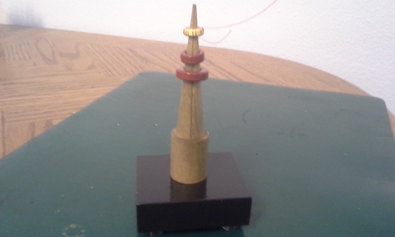
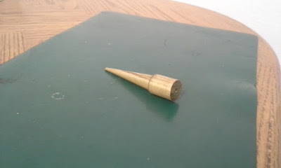
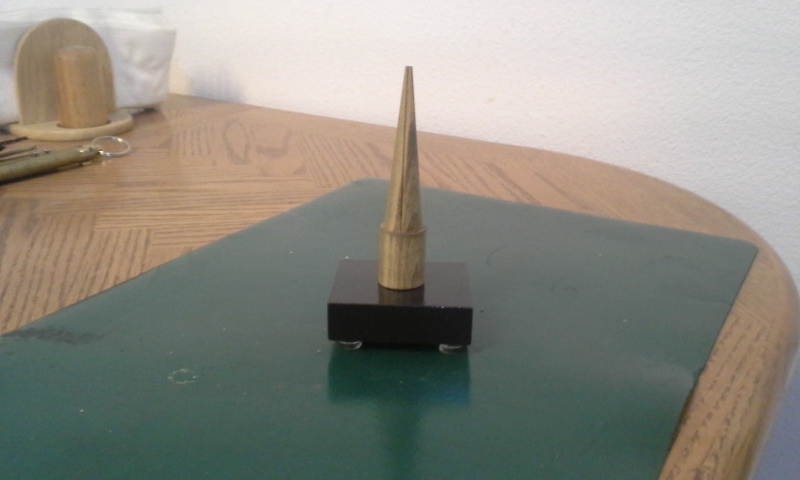
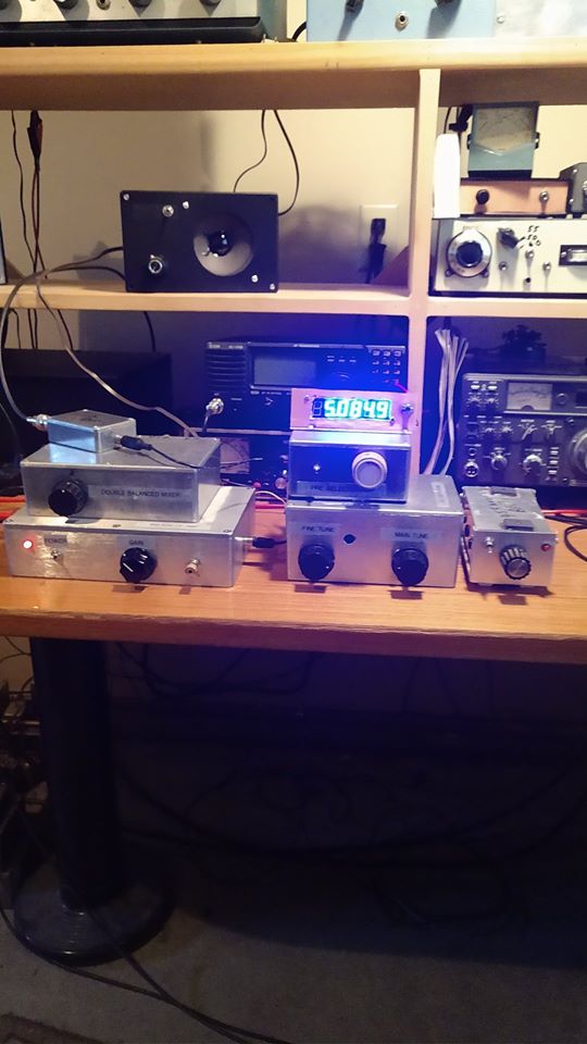
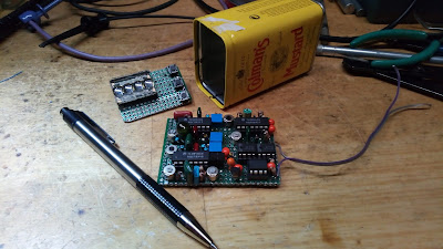
Its been a while. Lately I’ve been working on a phasing transceiver

that fits in a tiny can. Its called Hot Mustard. You need hot mustard

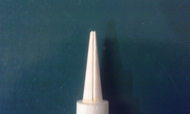
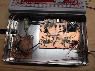
when you hamming. I finished the phasing board, its 10 poles , 5 in each

phase branch. here is a pic. Building the cpu board

next. I’ll document this one for a change hihi.
73,

Keith N6ORS

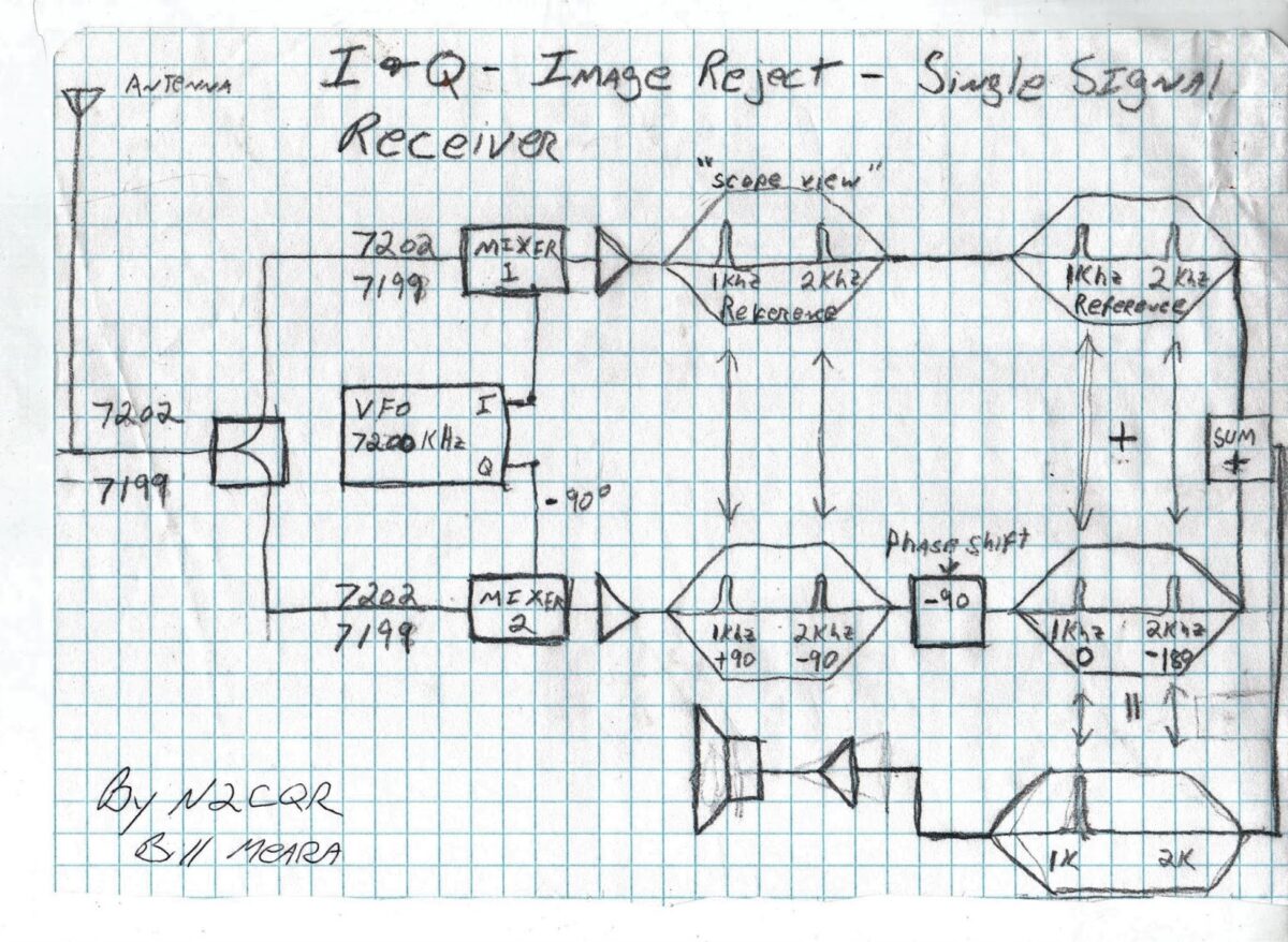
A while back I did a little diagram that — for me — explains how phasing cancels one of the sidebands. It appears below. I think Keith’s board is for the 90 degree audio phase shift. You can see how, by changing the shift from you can affect the degree of sideband suppression. I guess by going from -90 to +90 you could completely switch sidebands.

This diagram shows a direct conversion receiver with the VFO tuned to 7200 kHz. There is a signal at 7202 kHz and another signal at 7199 kHz. In a simple direct conversion receiver, BOTH these signals would produce audio tones in the receiver output. You’d hear both a 2 kHz tone and a 1 kHz tone. Assume you only want to hear the 1 kHz tone resulting from the 7199 kHz signal. Phasing lets you do this. Here’s how:

— First split the VFO signal into its “normal” output and an output that lags by 90 degrees (-90)
— Consider the output from the top (normal) mixer to be your reference signal.
— Because of the lag in the VFO signal going to the bottom mixer, the output from the bottom mixer will have the 1 kHz signal 90 degrees ahead of the reference signal (+90) while 2 kHz tone will be 90 degrees behind the reference signals (see “scope view”) above. This is a consequence of the mixer math.
— Now, in the bottom signal path, shift BOTH audio tones by -90 degrees (in relation to the top reference signal). I think this is what Keith’s board is doing.
— With this -90 degree shift, the 1 kHz signal on the bottom path will be IN PHASE with the 1 kHz signal at the top. But the 2 kHz signal in the bottom path will be 180 degrees OUT OF PHASE with the (top) reference signal path.
— The two signal paths are combined before going to the audio amplifiers. The 1 kHz signal is reinforced while the 2 kHz signal is “nulled out.”

The same principle can be used on transmit. Instead of two receive mixers, you have two balanced modulators. Both are putting out upper and lower sidebands. Instead of the VFO you have the carrier oscillator. By using the same phase shifting techniques you can reinforce one of the transmitter’s sidebands while nulling out the other.


A Toroid Winder from the Wizard of Wasilla — Paul KL7FLR

Paul KL7FLR has been sharing tribal knowledge with us for several years now. He recently provided insights on how to tap threads into metal. In 2017 he told us about his Alaskan road-kill microphone. And in the midst of the current quarantine he built this really neat toroid winding tool. Winding coils is often a show-stopper for would-be homebrewers; Paul’s device should help then get past this perceived impediment. Thanks Paul!

Paul writes:

A few weeks ago I needed a way of holding a T37-6 toroid to wind an LP filter coil. Being of the fumble fingered crowd I slapped together a quick and dirty holder using a crudely tapered ¼” wooded dowel. As fate would be, I soon needed to wind some other coils of a larger diameter and my wham bam holder wouldn’t do the job. Time to make a holder for more than just one size with the materials I had on hand.

I measured the id of the smallest toroid and the largest toroid I had and plugged them into an online taper calculator. https://www.easycalculation.com/shapes/taper-degree-calculator.php. Calculated taper was 6.65 degrees so I settled on an even 6 degrees with a length of 1 1/2”. The final of the taper was extended to 3”. Using my small 6” metal lathe I set the compound to 6 degrees and chucked up a 4” piece of a ¾” wooden dowel. I would have liked to have an ash, maple or other hardwood dowel but I used what I had on hand. Then I turned the 6 degree taper for 3” until the smallest end was 1/8” making the large end almost ¾”. Some sanding with 320 grit sandpaper followed by some ultra-fine 400 grit made it ready for a coat of clear sealer and a quick stain.

Moving over to the milling machine, I set the 6 degree angle with a 6 degree parallel in the vise. Positioning the mill spindle to the center of the dowel I used a #0 center drill to mill a slot the entire length of the taper to about .015” deep as I didn’t have a 1/32 end mill. This slot also can be accomplished with a rotary tool or a hobby knife and a steady hand.

I had a couple of 6-32 wood brass insert nuts in the hardware bins. Believe I bought these at Lowes and the Hillman part #880546 is what I used. Drilling a 3/16” diameter hole ½” deep I screwed the insert in until it was flush with the bottom of the dowel. My previous toroid holder had a wooden base but it proved to be too light and easily moved around on my bench. I dug out a scrap hunk of ¾” steel about 2.5 inches square. I then drilled a hole through the base using a #27 drill. Now the toroid holder can be mounted on the steel base using a 6-32 machine screw about 1 ¼” long and removed for a different size spindle when necessary. A wood base can also be used with appropriate length wood screw. Be sure to drill a pilot hole large enough in the spindle to prevent from the wood screw from splitting the spindle. A #6 wood screw long enough to pass through the base and into the spindle about ½” would be adequate.

Winding consists of passing the wire up (or down) the slot, lifting the toroid up and rotating slightly and back down on the spindle for the next winding. This has proved to be a very useful fixture when needing to wind some toroid coils.

The picture at the top shows a T-37-6, T50-2 and a T68-2 top to bottom. Will also fit a up to a T-106. Any larger toroids would require a larger spindle to be made.
Enjoyed your YouTube “Quarantined Receiver” and all the doings from Pete.
Paul
KL7FLR

Idaho Homebrew — Brian KE7LOY

Brian wrote (on Facebook):

This (above) is a general Shortwave Superhet receiver I built over the winter. I chose to go modular so I could interchange some of the modules and make easy repairs and changes to the circuits. I used discreet components and only 2 integrated circuits. I built a Colpitt’s buffered oscillator which is remarkably stable, a Gilbert Cell Double Balanced Mixer, a high pass filter to filter out local AM broadcast station. The IF chain uses an old classic collins 455 khz mechanical filter amplified by a J310 feeding into an MC1350P IC… It’s using 2 germanium diodes as a detector feeding into an LM386 output amp. It’s very, very selective and sensitive. I added a 455 khz BFO (lower right in pic) the other day to tune in SSB and CW. This has been a fun experiment.

10 Meter Quarantine QSOs near Boston — KC1FSZ’s Peppermint 10

Hi Guys:

I hope all is well. Thanks for the more frequent episodes!

I’ve not submitted anything lately but I’m still doing a lot of building. Over the last few weeks I’ve been working to get myself on 10 meters. There is some good local activity up here in the Boston suburbs on 10. The result of this effort is the next in the Peppermint Line of high-performance radio products for the discerning operator: The Peppermint 10. This rig uses digital VFOs and puts out about 12 watts on a good day. It works in conjunction with a direct-conversion receiver that has been modified for 10 meters. The details are described in the write-up (see link):


73s,

Bruce KC1FSZ