
I think we should start calling these “Quarantine Rigs.” Many of us are pulling off the shelves rigs that we started a while back but then put aside. Now, with the pandemic, we have the time (and the need!) to work on them.
I like Peter’s BITX receiver video, especially the part in the beginning where he wipes the grime and oxidation off the long-neglected copper-clad board.
Follow Peter’s lead: Pull those old projects off the shelf. Get them going. Now is the time. SITS! Melt solder and flatten the curve.
Thanks Peter.
Month: March 2020
Paul VK3HN’s Portable Rig
Nice work Paul.
Excellent Video on Maxwell’s Equations
Really well-done. He gets to the essence without getting bogged down in the math. Great graphics too.
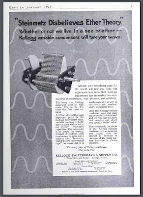
How They Make Chips That No One Can Understand
The December 21, 2019 edition of The Economist had an article about the Taiwan Semiconductor Manufacturing Company’s plant known as Fab 18. In just a few paragraphs the article explains something that I have been wondering about: We hear that some of the modern chips have millions, or even billions of transistors on them. Who could possibly design at that level of complexity? The article provides the answer: humans don’t do it. These chips are really designed by other computers (see above).
I don’t like to use integrated circuits because they often seem like mysterious black boxes I want to be able to understand how the rig I build really works. Some ICs do allow for this kind of understanding — you can get the internal wiring diagrams for an NE602, or an LM386, for example. You can study them and gain an understanding. Those little black boxes then become less mysterious. But that kind of understanding is just impossible with the kind of modern microprocessors churned out by Fab 18. No one really knows how these chips work:
“The circuitry is not as complex as, say, the human mind, but it is far more complex than any human mind could fathom.”
Sorry, but I prefer fathoming. Please pass me some 2N3904s.
Radio History Question: Why 455 kHz as the IF frequency?
My work on the S-38Es, on the HRO-dial receiver, on the Mate for the Mighty Midget, and on various mechanical filters has caused me to think (once again) about why we ended up with 455 kHz as the IF frequency for so many radios. I’ve heard many explanations for this, but unfortunately I’ve forgotten the explanations and lost the sources. I started digging into this again today. I found the below e-mail from Al N3FRQ on the Boatanchors mailing list (2008).
I contacted Al to find out if he had learned anything else on this topic. He has not. So if anyone out there has answers to Al’s questions, or anyother info that would shed light on why they went with 455, please let us know.
——————————-
Every so often the question comes up: Why are all the IF’s 455 KHz? I’d like to get an article together that solves this riddle while the people who know are still with us. I know parts of the story, but I need help with a couple of issues. There are two major consideration is the choice of the intermediate frequency used in a superheterodyne receiver. The lower the frequency, the easier it is to attain high selectivity. Also, in the early days, before tetrode and pentode tubes, it was easier to achieve a high degree of amplification at lower frequencies. Conversely, a higher IF frequency results in better image rejection. Early superhets had the IF at 100KHz or lower in order to get adequate gain from the available triode tubes. They suffer severely from “two-spot tuning” (images). By the early 1930’s, broadcast set had settled in at 175KHz, and automobile receivers would later adopt 262KHz as a standard. The advent of the short-wave craze, and multi-band broadcast receivers dictated a higher IF frequency to achieve adequate image suppression on the short-wave bands. The broadcast band occupied 550-1500KHz at this time, and the designer encounters sever problems if his radio tunes across it’s own IF. Some shortwave sets used 1600-1700KHz for better image rejection, but one couldn’t go higher if the 160-meter ham band (1800-2000KHZ) was to be covered. Most multi-band receiver settled in near 450KHz, a comfortable distance from the first broadcast channel at 550KHz. Questions: Odd multiples of 5KHz, 455, 465, etc., were usually chosen so that the image of the carrier of a broadcast-band station could be zero-beat with the carrier of the station being tuned to achieve minimal interference. (This assumes 10KHz channel spacing. Did the Europeans (9KHz) do something else?) The Radiotron Designers Handbook, Third Edition, p. 159, states “A frequency of 455 Kc/s is receiving universal acceptance as a standard frequency, and efforts are being made to maintain this frequency free from radio interference.” (1) Do FCC and international frequency allocations reflect this? (2) I’ve heard the term “Clear-Channel IF.” Can anyone cite references? (3) At lease one news group posting claims that broadcast frequencies in a particular market are assigned to prevent strong inter-modulation products from falling near 455KHz. Is this factual? Need reference.” (4) Was this (3) at least part of the reason for “Radio Moving Day” in 1941? See: http://www.dcmemories.com/RadioMovingDay/ 032341WINXFreqChange.jpg (5) Many National Radio sets used a 456KHz IF’s and I think I remember a 437 somewhere. Why? Are there different considerations for short-wave CW operation? Further input, corrections, and elaborations are greatly appreciated. Scolarly reference will be looked upon with great favor. Regards, Al -- Al Klase - N3FRQ Flemington, NJ http://www.skywaves.ar88.net/
Mr. Carlson Restores an All-American Five — Tribal Knowledge! SITS! Flattening the Curve! (video)
It is always a pleasure to see a new video on Mr. Carlson’s awesome YouTube channel, especially in these days of Staying-In-The-Shack (SITS). Obviously Mr. Carlson is doing his bit in this area. FLATTEN THE CURVE! Thanks OM!
My recent bout of S-38E madness has peaked my interest in the All American Five design, so this March 10, 2020 video was especially interesting to me. Mr. Carlson puts out so much great tribal knowledge. I didn’t know about “rounder” resistors. I didn’t know that you have to be careful not to short out (to the IF can case!) the 455 kc transformers. I really like his approach to dial cord restoration.
Mr. Carlson’s discussion of the adjustment of the front end tuner circuit on this broadcast band radio was very interesting. Unlike the S-38 radios, there are no front end coils being switched in as you change bands. In fact, it appears that that big coil/antenna inside the back cardboard piece IS the front end coil. This discussion has caused me to question my front end alignment technique for the S-38E. Did I have an appropriate antenna or antenna substitute across the antenna terminal when I set the peak on the input LC circuit? I will check on this. Hooray! One more thing to do during the COVID-19 SITS period.
UPDATE: I checked on this using the test set up described in an earlier post, but this time with my antennas connected. First with a 40 meter dipole, then with my 130 foot doublet, then with a 50 ohm dummy load I was still able to see the resonance dips at exactly where I wanted them to be.
My favorite bit of Carlsonian wisdom from this video? Mr. C’s confirmation that some hum in All American Five receivers IS NORMAL! (This may be too much for the folks who find normal band noise to be offensive.)
For Inspiration and Education: Dean’s Radio Blog (with video)
Be sure to check out the blog of Dean KK4DAS. He is a new homebrewer who is having great success with one of Pete Juliano’s ingenious SSB designs. Dean has a video of his receiver working — AL FRESCO — as construction on the full transceiver proceeds.
This is amazing. Just a short time ago Dean was taking his first steps as a homebrewer with his version of the Michigan Mighty Mite. He has followed the advice of the Tribal Wizards and has proceeded slowly, step by step, stage by stage, gaining the experience that has allowed him to actually build a superhet receiver and be on the verge of completing a full SSB transceiver.
Lots of inspiration to be found on Dean’s blog. Check it out:
https://kk4das.blogspot.com/2020/03/dean-kk4dass-furlough-40-ssb-rig.html
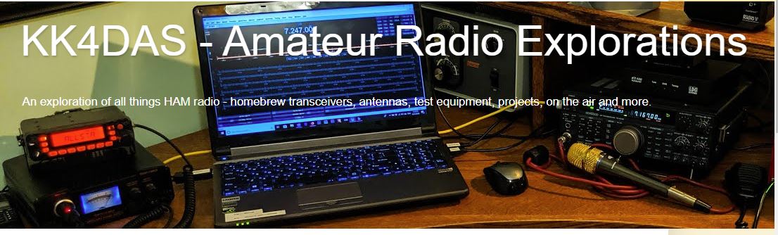
Technical Manual 11-455 — Radio Fundamentals — July 17, 1941
This is an illuminating little book. It was published by the U.S. War Department on July 17, 1941, less than five months before Pearl Harbor. Far from being dated, this book contains a lot of great explanations of — as the title indicates — the fundamentals of radio. I turned to it this morning for a little refresher on the physics of regenerative feedback.
You can get your own paper copy here:
Or here:
Or you can read a slightly more recent edition (1944!) online (free) here:
Please let me know if you find this book useful.
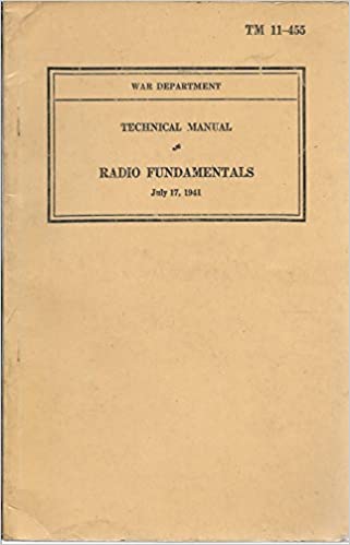
These Variable Capacitors Work — Ether or No Ether!
Amazing that the arguments about the presence or absence of a luminiferous ether made its way into parts advertisements in a radio magazine. This is from Radio for January 1923. (About 18 months before my dad was born.)
BTW that capacitor looks very nice, and would almost certainly still work. I have caps like that in my junk box. The shape of the blades helps address one of Pete Juliano’s complaints about analog oscillators — the inconsistent spacing of frequencies on the dial.
Thanks to the K9YA Telegram for posting this.
COVID-19 — StayInTheShack (“SITS”) — Our Contribution to Flattening the Curve
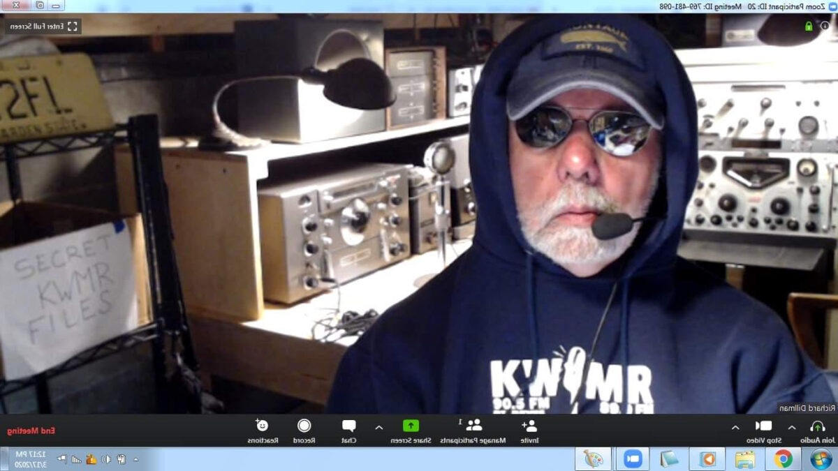
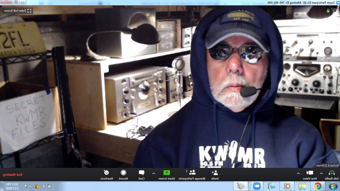
Early in the COVID-19 Emergency, I saw this inspiring picture of Dick Dillman W6AWO. Dick had placed a caption under the picture: “I’ve moved to the command bunker and will be staying here for the duration.” That’s the spirit OM! That is what we as radio amateurs should be trying to do at this point. That is how we can help flatten the curve and slow the transmission of the virus.
I guess we could call this #SITS: Stay-In-The-Shack. For many of us this is really not much of a sacrifice — this is what we mostly wanted to do anyway. And we have people to talk to (on the air).
So… Follow OM Dillman’s lead. FLATTEN THE CURVE! STAY IN THE SHACK!
73 and take care.
AM Diode Detector + 41 and 49 meter Shortwave Bands for HRO-dial Receiver (videos)
The COVID-19 emergency is a good time to look around the shack for projects you have been meaning to take on but didn’t have the time for. We have the time for them now!
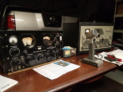
When I first built my HRO-dial receiver (using an HRO dial given to me by Armand WA1UQO and an enclosure from Tim KI6BGE) my hope was to have the 40 meter ham band and some shortwave broadcast bands. But it didn’t work out that way. I had trouble getting an AM detector to work properly, and I had a hard time getting a sufficiently broad filter to work right. I ended up adjusting the VFO so that the receiver would cover only the 40 meter ham band.
My recent S-38E adventures and a video from VK3HN have alerted me to the nice programming that is now on the shortwave broadcast bands (I really like WRMI’s afternoon rock music program). So I decided to take another shot at getting this receiver to cover SW BC frequencies.
When I built this receiver, I made the front-end bandpass filter tune-able. There is a two section variable cap behind that “Pre-selector” control you see on the front panel. That lets me tune two loosely coupled LC circuits from about 5.5 to about 8 MHz. So without any mods to the front end, I could cover the 49 meter band (5.9 — 6.2 MHz) our 40 meter band, and the 41 meter band (7.2-7.5 MHz)
Here is how I do it:
For 49 meters: I now have the VFO set to run from 6.34 MHz to 7.120 MHz. The IF is .455 Mhz. So to get down to the lowest frequency in the 49 meter band, I tune that front end preselector down to that frequency (variable cap in filter almost fully meshed). Then I take the VFO down to 6.355 Mhz. I take the difference frequency out of the mixer — .455 MHz.
For 40 and 41 meters: I just tune the pre-selector to this range (variable cap about mid-range) and tune the VFO accordingly. For a signal at 7.5 MHz, for example, I put the VFO at 7.045 MHz. 7.5 – 7.045 = .455 Mhz. Note: There is no sideband inversion in this case — this is important because 40 meter SSB is lower sideband. The Kokusai mechanical filter that Pete N6QW gave me is a lower sideband filter. I have my BFO set at the right spot relative to the filter passband for LSB.
As you can see, I just tune to the “image frequencies” with the preselector. This gives me double the frequency coverage.
As for the filters, well Pete’s Kokusai filter works great on 40 SSB. My problem was, ironically, getting a filter that was broad enough to let AM sound good. I concocted a filter using old 455 kc IF cans, but I wasn’t happy with it. Paul VK3HN used a ceramic .455 MHz filter that was 6 kHz wide at 6 db down. I ordered some from Australia. That should have been wide enough for AM, but I had gotten spoiled by the very WIDE bandwidth of my S-38Es (no real filters at all, just the two 455 kc IF cans). At this point The Radio Gods interceded. Bruce KK0S heard me talking about this on the podcast and kindly sent me some 10 kHz .455 kHz filters. Now we’re talking! I put one of them in this receiver and AM started sounding as good as it does in my S-38E. BTW — a look at NA5B’s WebSDR receiver shows that most of the SW broadcast stations are running at 10 kHz wide. See video below:
Finally, I had to get a decent AM detector going. The SBL-1 product detector I have in there works great, but I had tried several AM detectors and none of them worked well for me. This was puzzling — it should be so simple, right? Just a diode. But I would get weak and/or distorted audio. I realized that I really needed was something that looked to the rest of the circuitry like an SBL-1, but with just a diode and an RC filter section instead of the SBL-1’s diode ring. I ended up using a small 455 kc IF transformer that Michael Rainey (AA1TJ) had sent me a long time ago. My detector looks like this:
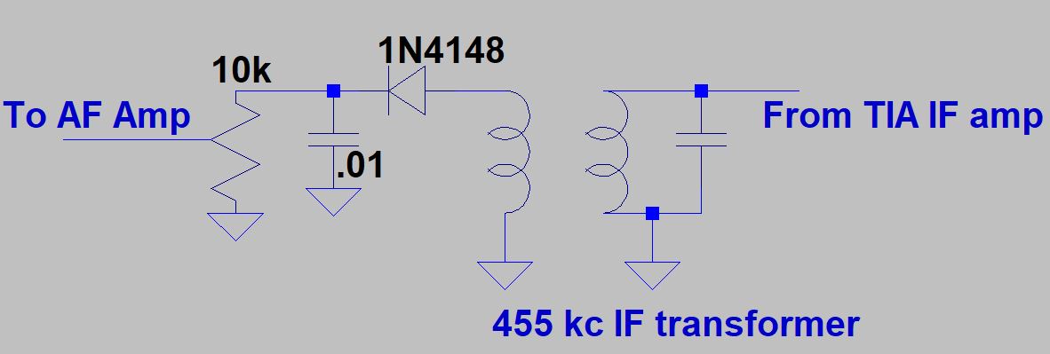
It works great. During the day I can hear the Toronto CFRX talk-radio station that simulcasts with 1 kW on 6.07 MHz. In the evening I her WBCQ and many other stations on 41 meters (see videos). And of course I am ready to use it for amateur AM signals on the high end of the 40 meter phone band.
There is a lot of soul and friendship in this receiver:
— HRO dial from Armand WA1UQO
— Aluminum box from Tim Sutton KI6BGE
— Mechanical Filter from Pete N6QW
— IF transformer from Michael AA1TJ
— Ceramic filter from Bruce KK0S
— 10k pot in the detector from Thomas KK6AHT
— Inspiration and ideas from Paul VK3HN
— Many parts from Jim…
But you know, I find myself thinking that there are many stations I like on the 39 meter band. I think it might be best to build a separate receiver for those frequencies. Maybe throw in 30 meters. Hmm, let me see what’s in the junk box…
Will, KF4IZE’s Beautiful Boatanchors
Wow, check out the paint job on that SP-600. Nice work Will. Hammarlund should have done it that way. And I should have kept the one I had years ago. I would have painted mine that way.
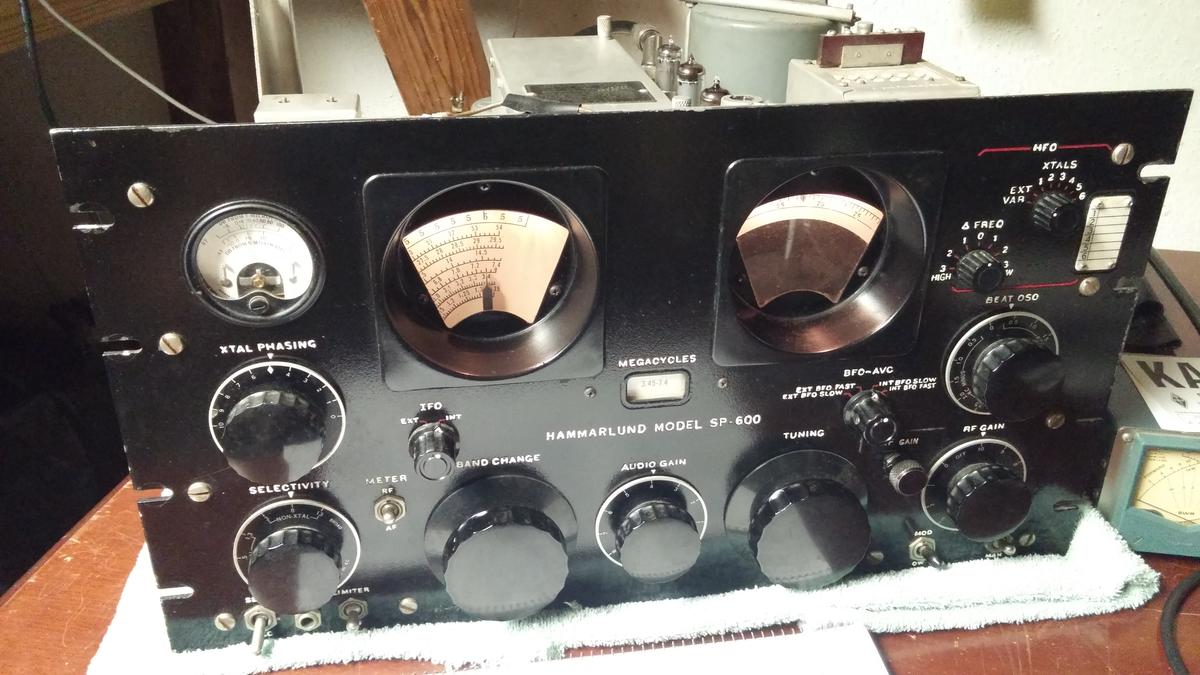
And my DX-100 (given to me by John K2ZA) has similar vernier reduction drives.
I run into Will KF4FZE fairly often on 40 meters. He and I were in the same (very cool) part of the U.S. Army (in different times). Will is retired but he still works at Ft. Bragg.
I heard Will on 40 SSB yesterday afternoon. I was listening with my HRO dial receiver (that I am now working on). I shot quick video:
Will was on a Swan Cygnet 270 that he had recently picked up on e-bay.
More on Will KF4IZE here: https://www.qrz.com/lookup/d/kf4ize
Vernal Equinox Today — Earliest in 124 Years

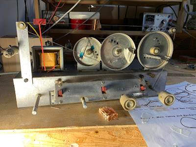
Double Trouble: Notes on TWO Hallicrafters S-38E Restorations and Alignments (with videos)
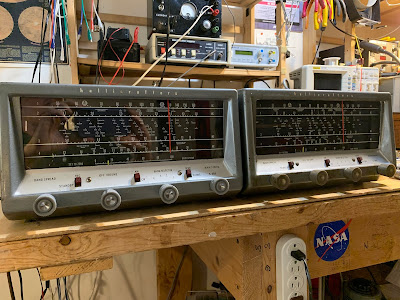 |
| Winterfest S-38E on the left, junker on the right |
I have been talking bad about the Hallicrafters S-38E receiver for several years now. For a long time I agreed with my friend Pete Juliano in his colorful description of the receiver: “a pig with lipstick.”

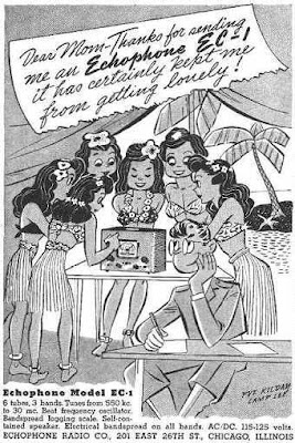
But as I’ve gotten to know the receiver better, I have come to like it. It is very simple. There is a certain minimalist thing that explains the attraction; it is a challenge to make the most of this very low-budget 1950’s receiver. It uses tubes, but the voltage is not really in the very lethal range. It covers a wide range of frequencies. Its frequency stability is fairly good. And it sounds great on AM (scroll to the bottom to listen). It seems to be technologically related to the Echophone EC-1 — we have been posting about the WWII advertisements featuring Hogarth and his (unbelievable) efforts to attract women with this receiver.
The S-38E has a big “picture window” frequency dial, marked with exotic foreign locations (Java!). I share with it a similar vintage with the S-38E: IGY. The S-38E was produced from 1957-1961. Duck and cover my friends; the CONELRAD frequencies are marked on the dial. Working on these two receivers has kept me busy during the first few days of the COVID-19 emergency.
I now own two of these things. I might get a third. I thought it would be worthwhile to write up my experiences with the S-38E. I hope this information will be of use to others who might work on this piece of gear.
 |
| Winterfest RX on the left, junker on the right |
SHOCKINGLY BAD?
I had an S-38E as a kid. Around 1980, I gave it to my cousin Mary’s husband Mike so he could listen to shortwave broadcasts. Recently I asked him about that S-38E — he said it had given him a nasty shock. That was because of the “transformer-less” AC/DC power supply — if you plugged the AC line cord in “the wrong way” you would be putting 115 V AC on the chassis. Ouch.
AC/DC DESTROYS AN ANTENNA COIL
I picked up an S-38E at a Vienna Wireless Winterfest a few years ago. I think I paid ten bucks. I didn’t pay attention to the polarity of the AC plug and managed to plug it in the wrong way. Then I managed to short the antenna terminal to what turned out to be a very AC hot (115V) chassis. This destroyed a significant portion of the antenna coil. Smoke was released.
ISOLATION TRANSFORMER
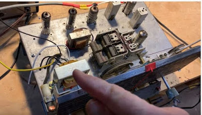
Not wanting to repeat the hot chassis disaster, I installed an isolation transformer. On the junker, I used the Triad N-49X, available from Digikey. In retrospect I probably should have gone with the larger, 35 watt N-51X, but Fred KC5RT provided a great suggestion that would make the smaller N-49X adequate: Run the filaments in series DIRECTLY from the AC line, with neither side of the AC line to the chassis. Then run the rest of the circuitry through the isolation transformer. This would take a lot of current out of that little transformer and would likely make replacement with a larger unit unnecessary. I will try this later. Update: 2 April 2020: I tried to run the S-38E with the filaments in series fed with AC directly from the line cord and the rest of the circuit running through the isolation transformer. I got it working this way. Sort of. But AC hum was a lot louder and I found myself back in the AC/DC transformerless situation with the chassis going hot if the set is plugged in “the wrong way.” So I retreated, going back to having the whole receiver running off the isolation transformer. The hum went back to the earlier (normal) level and the chassis would not go hot no matter how I plugged it in.
On the Winterfest S-38E it looks like I had used a larger isolation transformer.
I put a 500 ma fuse in the primary circuit. On the N-48X the black lines are primary, the red are secondary. One black line goes to the fuse, then on to the front panel on/off switch. The other side of the switch goes to the AC line. The other side of the AC line goes to the other black line. Neither of the AC lines goes to chassis. On the secondary side, one of the red lines goes to Pin 4 of V5 (rectifier); the other goes to the B- line which is Pin 3 of V3 the 12AV6 which is also connected to the volume control. I put the isolation transformer on the top side of the chassis. It ends up close to the speaker, and fairly close to the AF output transformer. This raises hum concerns.
| Where I placed the isolation transformer on both my S-38Es |
HUM?
I did a test to see if my placement of the isolation transformer was adding to the hum. I simply took the S-38E back to its original transformer-less configuration and then listened to the hum. I noticed no difference and concluded that the isolation transformer is NOT adding to the hum. If there is a difference, I’d say that there is less hum with the isolation transformer. (And yes, I did make sure the AC line plug was in the correct way with the old power supply configuration.)
See what you think:
The hum is not really a problem. You can only hear it when the volume control is turned all the way down. As soon as you turn the volume control to the right, band noise overwhelms the hum and you can’t hear it any more. I think this was the normal condition of this very economical receiver.
The two receivers have different speakers. The Winterfest speaker measures 7.6 ohms (DC) and the junker has a 3 ohm speaker (closer to that called for in the schematic). I think the 3 ohm speaker results in somewhat less hum.
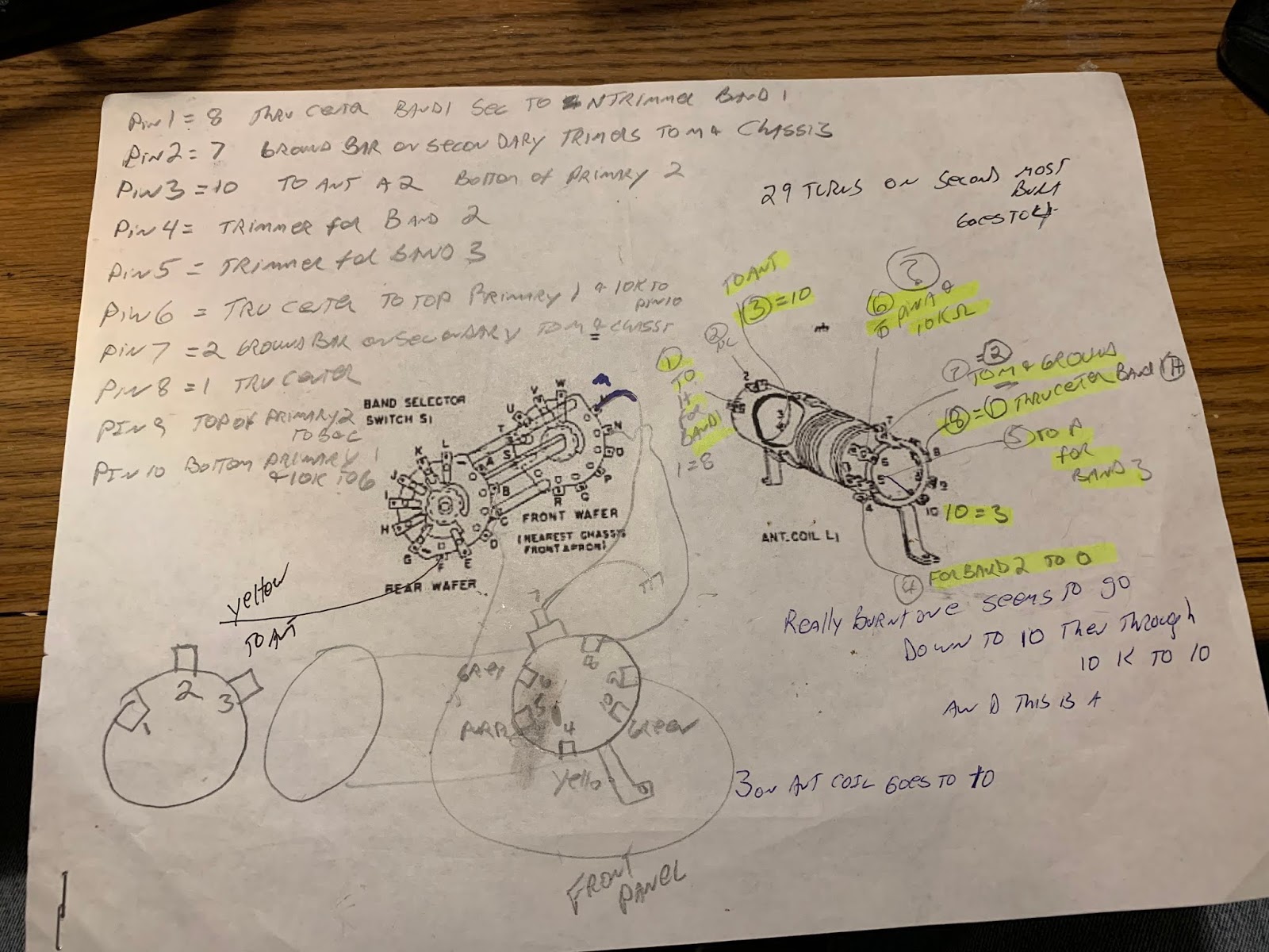
REPAIRING/REPLACING THE ANTENNA COIL
After the smoke release, I tried to re-wind the burned out portions of the antenna coil on the Winterfest S-38E, but I got tired of the project, cursed all S-38s, and sent mine to the basement/crawl space. I would have given it away, but I was afraid that the recipient would electrocute himself. So it sat in the basement for a couple of years. Recently I got interested in shortwave listening again, so I pulled out the S-38E.
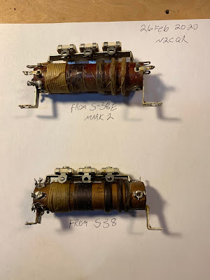
On e-bay, I found and bought an S-38 antenna coil. I put it in my S-38E, hoping that it would bring the receiver back to life. But I had a lot of trouble with the front end alignment. I theorized that the coil I had bought was from the original model of the S-38, and perhaps the S-38E coil had different inductances. So I went back to e-bay. There I found a junker S-38E being sold by Mark W1MEM. It had been owned by KA1WFY.
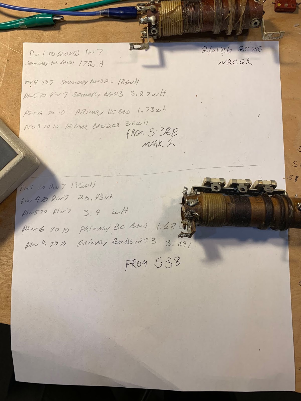
At the suggestion of Scott W1NB on the AntiqueRadio forum, before installing the coil from the junker, I measured the inductances of the S-38E coil and the previously obtained S38 coil. I was surprised to find that the values were almost identical. That meant that my theory about coil inductance differences was incorrect. But I took the S-38E coil from the junker and put it in my S-38E. I took note of the fact that the junker did not in fact look like junk, but there it was, sitting on the floor of the workshop, having had its antenna coil extracted. And I had in hand the old S-38 coil that I knew from testing was very close in value to the S-38E coil.
I was kind of getting tired of S-38s at this point, and I thought about leaving work on the junker S-38 for another day (or another year, or decade), but familiarity with the innards of the rig and alignment procedures is perishable, so I decided to try to get the junker going while it as all still fresh in my mind. I installed the isolation transformer mod on the junker and put the S-38 antenna coil in. That is how I came to own a second S-38E.
RF ALIGNMENT PROBLEMS
One of the problems I had was that the alignment instructions for the S-38E are very sparse. For the front end alignment, they just tell you to put signal generator signal into the antenna terminal, put a meter or scope on the audio output then tweak the antenna and oscillator coils for max output. I had no trouble getting the oscillator on the right frequency — for bands 2 and 3 that would be the signal frequency PLUS .455 MHz. For Band 4 it would be signal frequency minus .455 MHz. But I could not get the LC circuit in the front end to peak on the input frequency. Now, if you have the peak for the input LC circuit in the wrong place, your receiver will still work (sort of) but image rejection will be even more horrible than it is designed to be.
For example, assume you want to tune a strong signal at 7.0 MHz. Your VFO is at 7.455 MHz. The difference frequency is .455 MHz. This signal goes through the IF transformers and you hear the signal.
But now tune down .910 MHz to 6.09 MHz. Your VFO will be at 6.545 MHz. 7.0 – 6.455 = .455 Unless the front end LC filter blocks the strong signal at 7.0 MHz, it will also show up at 6.09 MHz on your dial. If the S-38E is aligned properly, that front end LC circuit will track the tuned frequency. In this case it will be peaked at 6.09 MHz and the strong signal from 7.0 MHz will not get through. Oh happy day! That 7.0 MHz signal shows up only on one place on the dial. All is right with the universe.
Of course there is another image problem. If you are tuned to 3.9 MHz, your VFO is at 4.355 MHz. If a shortwave broadcaster fires up on 4.81 MHz, well 4.81 – 4.355 = .455 That is why I can hear “Brother Stair” raging away, seemingly at 3.9 MHz. Even if a simple receiver like this is properly aligned, a powerful shortwave broadcast signal will often get past the puny single LC circuit in the front end.
But what happens if the S-38E is misaligned? What happens if that LC circuit is peaking above the desired frequency?
Now when you tune to 6.09 MHz, the front end tuned circuit may be peaked at say 6.5 MHz. There is only one tuned circuit in this receiver front end, so the “skirts” are quite wide. Wide enough to let that 7.0 MHz signal through to the mixer where it mixes with the 6.545 MHz VFO output to produce a very audible output. This is what was happening when my S-38E was misaligned. The 40 meter ham band and the 75 meter hambands were both showing up at two places on the dial. After alignment, this problem disappeared.
I realized later what my problem was: I was putting far too much faith in the accuracy of the frequency readout needle on the front panel of the S-38E. Many of these receivers had had their dials restrung over the years, so in many cases the placement of the needle was significantly off.
MY RF ALIGNMENT METHOD
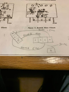
What you really need to do is this: At first, don’t pay much attention to where the red or yellow frequency indicators are pointing. View them as rough measures. Put a signal generator across on the A1 antenna terminal, with ground from the sig gen going to both A2 and GND. Then put a scope probe across the same A1 -A2/GND terminals. On Band 2 set your sig generator to, say, 4.0 MHz. Tune the main tuning dial UNTIL YOU SEE A BIG DIP ON THE SCOPE. At that point your front end is tuned to 4.0 MHz. Now, you need to set the oscillator coil to 4.455 MHz. I used a separate general coverage receiver (Radio Shack DX-390) tuned to this frequency. I slowly tuned the trimmer on the oscillator coil until I could hear the oscillartor on 4.455 MHz on the DX-390. At this point the front end is in alignment.
It might not be that easy at first. You may need to use the LC trimmer and the oscillator trimmer to kind of “walk” the two desired frequencies close to each other. But by doing this, I was able to get the LC circuit to peak at the frequency at which the VFO was .455 MHz above the freq at which the LC signal peaked (the desired signal frequency). Now, you may notice that the red frequency indicator is not at 4.0 MHz exactly.
Later I decided to tackle this problem of front panel calibration. I decided to only worry about Band 2 (1.6 -5.0 MHz) and Band 3 (4.8-14.5 MHz).
I picked two frequencies on these two bands that would use the same position of the red tuning pointer. (I put they yellow bandspread pointer at 0. ) I chose 9 MHz and 3.1 MHz.
For Band 3, at 9 MHz I set up my sig gen and scope as described above. With the sig gen on 9 MHz, I tuned the main tuning dial for a dip at 9 MHz. Then, keeping the tuning cap at the same spot, I moved the red pointer to exactly 9 MHz. (I just pinched the cord to the front panel with my finger and slid the red pointer down along the cord a bit. I then turned on my general coverage receiver, set it to 9.455 MHz and turned oscillator trimmer H (see above) until I heard the VFO at that frequency.
I then moved the S-38E to Band 2. I set the sig gen to 3.1 MHz. Leaving the main tuning cap and the red pointer exactly where they were, I tuned the antenna coil trimmer L until I saw the dip on my scope. I then turned the general coverage receiver on to 3.555 MHz and tuned oscillator trimmer K until I heard the oscillator signal at that frequency.
The S-38E was then aligned for RF on Bands 2 and 3 with fairly good front dial calibration.
Here is how to tell if you’ve got it lined up right. Tune to the 75 meter band on Band 2 or to the 40 meter band on band 3. Then tune 910 kHz BELOW where you found the ham band. Do you hear the ham chatter in that second location on the dial? If you do, the signal strength should be significantly lower than the signal strength 910 KHz up. If you don’t hear it at all, great. If you hear it at significantly reduced strength, that’s OK too. the S-38E has only ONE tuned circuit between the mixer and the antenna, so you can’t expect really great image attenuation. But if you hear the image at the same strength (or stronger!) than the desired signal, you have placed the peak of the antenna input tuned circuit in the wrong place. See above. Try it again.
IF ALIGNMENT
IF alignment was relatively easy: I put a 455 kHz signal onto the grid of V1 and my scope on pins 5 & 6 of V3. I then peaked the four IF transformer coils. The IF cans in he Winterfest receiver were close to .455 kHz. The coils in the junker were quite a bit out of tune.
RECAP
On the first S-38E I assumed that I would have to change out all the electolytics and the older tubular capacitors. So I did. But with the second (“junker”) S-38E my replacement capacitors from Hayseed Hamfest had not yet arrived. So I pulled out my Variac and made a somewhat hasty effort to re-form the original caps. It seemed to work. No smoke was released. Nothing exploded. There is no horrible hum. But I could tell that all was not quite right. The BFO really wasn’t oscillating properly. When the capacitor kit from Hayseed Hamfest arrived, I replaced all the caps. The receiver works great — including the BFO.
 |
| Recapping in process. Hayseed electrolytic in green can.. Old tubular caps being replaced by new yellow caps. |
 |
| Recapping completed |
ALIGNMENT OF THE JUNKER
Armed with my newfound knowledge of how to align an S-38E, I applied this skill to the junker and was able to get it aligned without difficulty.
RE-STRINGING OF DIAL CORDS
On both of these S-38-Es there were dial string problems. Interestingly, both problems were with the BANDSPREAD dial cord, NOT with the MAIN TUNING dial strings. I see this as evidence that these receivers were used by ham radio operators. You don’t really need the bandspread to tune AM shortwave station, or AM broadcast band stations. But novice ham radio ops would be frantically tuning that bandspread control up and down, wearing those dial springs out. The Bandspread dial string on my Winterfest S-38E broke while I was turning it — I replaced it but it is not really smooth, so I may try again. The Bandspread dial on the junker broke also.
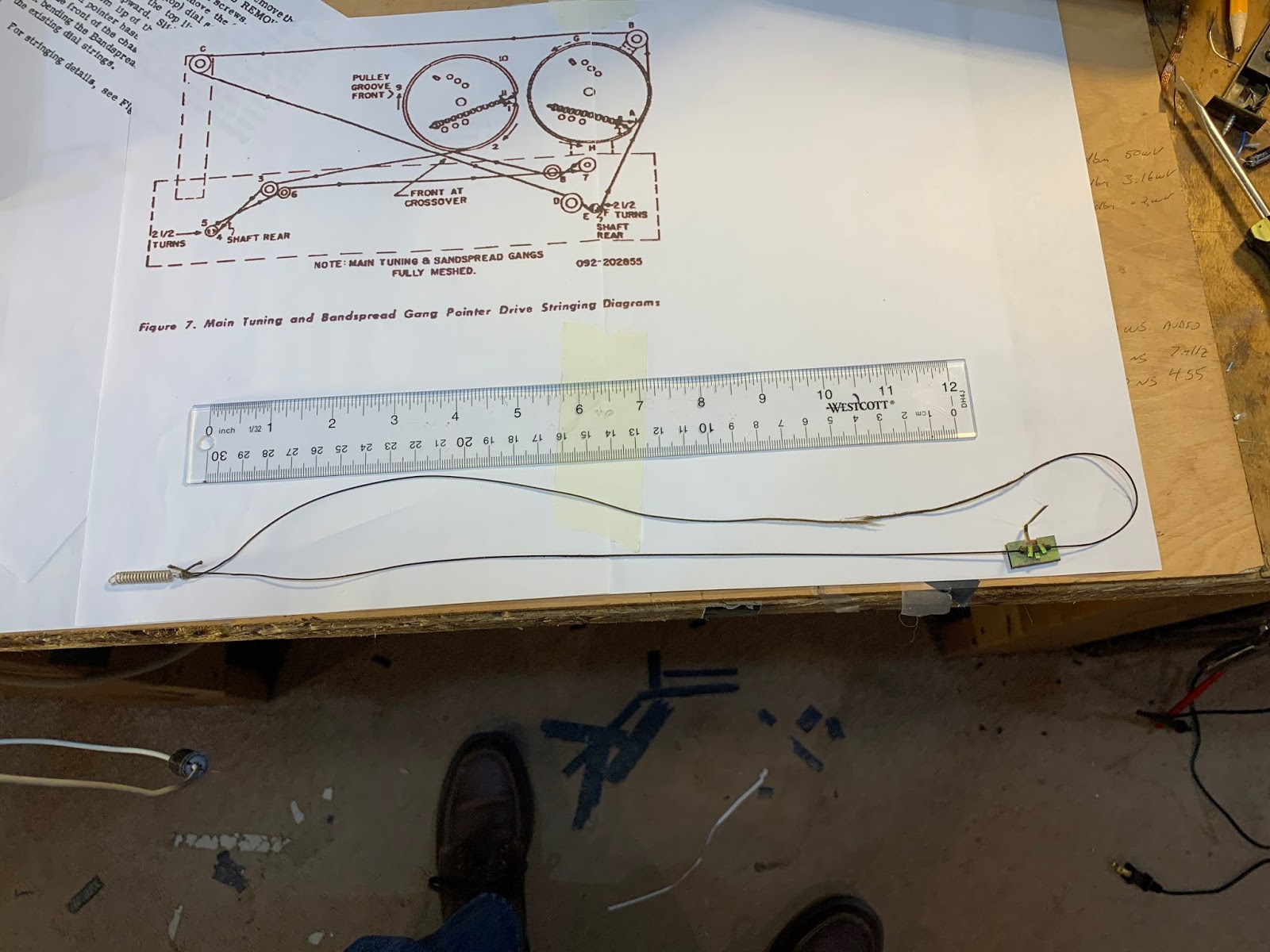 |
| Broken Bandspread string from Winterfest S-38E |
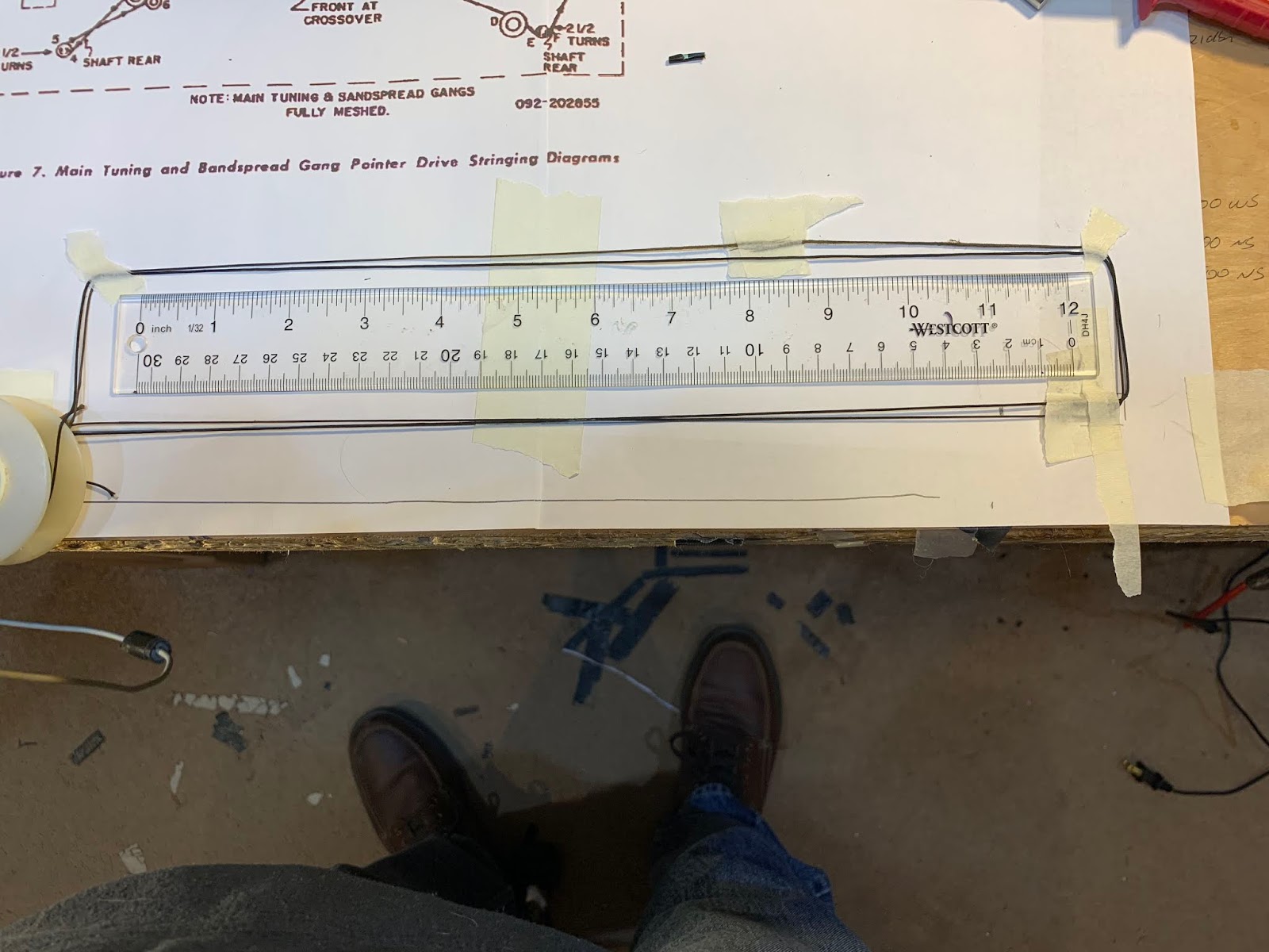 |
| Approximating the size for the replacement string |
My re-stringing skills were better the second time around. Tips: use a small file to “roughen up” the spindle on the tuning knob (just the center of the spindle, so it will grab the cord better). Before installing, rub the new dial cord with an isopropyl alcohol pad, then run the string (still a a bit wet) several times over a piece of violin rosin. This seemed to prep the dial cord well.
Sometimes you need a bit more tension on the string to get the tuning spindle to grip properly. Unlike the Drake 2-B, the S-38E does not have several hooks on which to attach the spring. Not wanting to have to start all over just to add a bit more tension on the string, I came up with an easier solution: Just put a few twists in the string near the spring by twisting the spring (with strings attached) around a few times. Like this:
You also need something that allows the indicator needle to grip the dial cord. I cut open a short piec of heat-shrink tubing, put it over the cord at the desired spot, hit it with hot air, then put a small dab of super glue at each end of the tubing. ( See above.) This allowed the dial pointed to grip the cord very firmly. Because you may need to move the red pointer during dial calibration (see above) I’d recommend NOT putting the drops of glue on the cord for the red pointer — you may need to slide the red one up or down a bit.
TUBES
On the Winterfest S-38E, the BFO had a very rough tone, making it impossible to copy SSB or even CW. I thought it might be a bad set of filter caps, but after I replaced them, the problem was still there. So I then replaced the tubes (warning — that 50CS audio amplifier is expensive). This fixed the problem
The junker had original Hallicrafters tubes.
LISTEN!
Here are some YouTube videos of the S-38Es in action:
Ham Radio — Practicing Social Distancing for over 100 Years!
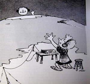
I really liked this picture.
Words to Live By — From Allan WA9IRS

SolderSmoke Podcast #219 SPECIAL CORONA VIRUS CRISIS PODCAST
SolderSmoke Podcast #219 is available for download:
14 March 2020
SPECIAL CORONA VIRUS EMERGENCY EDITION
We thought it would be nice to put out a special edition of the podcast to help listeners keep up their morale during this difficult time. So we’ll do our regular kind of show, but we’ll try to emphasize things you can do to stay busy and keep up morale while stuck at home.
BILL’S BENCH (and operating position)
–NOVICE RIG ROUNDUP. NRR. Continues through this weekend. Lots of fun. Cool rigs worked: Jon WS1K’s “Scrounger.” Greg AA8V’s 6X2 superhet. And WN4NRR.
— S-38 MANIA. My S-38E story. Bought parts. Bought a junker. Fixed the first one then used the parts to fix the junker. Now I have 2 S-38Es.
— Got capacitor kit from Hayseed Hamfest. FB.
PETE’S BENCH
Hilbert Transforms
AD9833 glued onto a Nano
Teesny and Radig and ZL2CTM
PWKSCDS
More Mint
SOME THINGS TO DO DURING COVID 19 CRISIS
WebSDR NA5B
Revive an old boatanchor
Get back into shortwave listening.
Get on the air—make some contacts!
Take a walk. Get some exercise. Listen to SolderSmoke and other podcasts when you walk.
Cook something from the famous Pasta Pete web site.
Help someone who needs help.
MAILBAG
QSP – What a cool magazine! Pete and I both have articles in there.
Hot Iron – great new issue also. Lots in there.
Tony Fishpool G4WIF Words of Wisdom on the NanoVNA.
Thoughts on How Hams Can Use the Shortwave Broadcast Frequencies
Ed DD5LP sent us some very interesting information about a resurgence of shortwave broadcast activity in Europe. Thanks Ed.
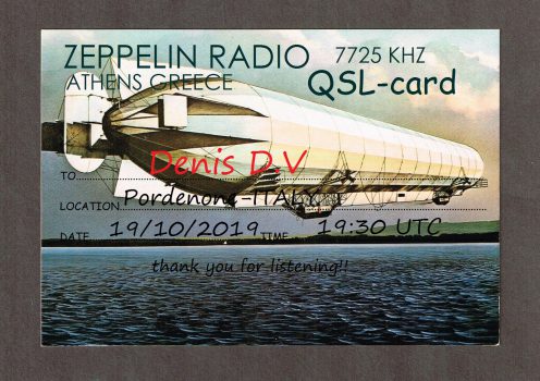
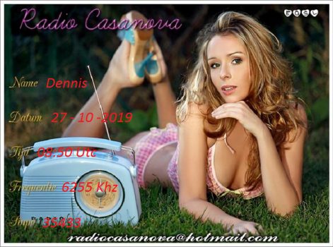
Here is a collection of QSL cards sent out last year by some of these new stations.
Hi Bill,
I’m just listening to the latest podcast and note your returning lovefor AM Broadcast stations and wondered if you also see the trend in the US that we are seeing in Germany?
I know you have WTWW but that’s a commercial SW AM Broadcast radio station, that has always been owned and run by a family of Hams. What we are seeing Germany is that when a commercial broadcaster such as Deutsche Welle closes down their Shortwave Broadcast stations, Amateurs are applying for and getting licences to the freed up frequencies. This started about 5 years ago with channel292 (Channel292.de) on initially 6070 kHz and then later also on 7440 kHz. This amateur is located near Ingolstadt in Bavaria and runs 10 kW using the driver stage from the old DeutscheWelle 100 kW transmitter on the same frequency. He is partnered with a group in Austria who run a major AM station near Vienna that has two 500 kW transmitters and some fantastic massive antenna systems with 20dB gain across the whole of the HF spectrum. That Austrian station is still owned by the Austrian government in case they need a broadcast station to transmit around the world at any time. It’s kept “idling” at 100 kW in the meantime and like Channel 292 includes the German language “DARC Radio” amateur radio program in what it transmits.
New on the scene is “shortwaveradio.de” – Yes the station name is the same as their web address. They currently run just 1 kW into an Inverted-V wire antenna on 3975 kHz (in the 75m BROADCAST band over here) and 6160 kHz in the 49m broadcast band. As they are located in North Germany, I don’t get much of a signal from them down here in the south and the recording is using a WebSDR receiver. Their dipole is orientated to cover the Benelux countries and the UK. The lads at this station are always looking for English content, so if you want part of Soldersmoke to be transmitted on a shortwave AM broadcast station, (as you mentioned in the latest podcast) I can easily put you in touch with them.
One more for the list could be Radio Caroline in the UK. The station, which once was the main pirate radio station off the coast of the UK is now a volunteer historic preservation society (with some radio Hams involved) who have been granted a local radio service licence using a frequency (648 kHz) and transmitter site previously used by the BBC world service! Their old nemesis ! (http://www.radiocaroline.co.uk/#home.html )
73 Ed DD5LP / G8GLM / VK2JI.
QSO Today Interview with Dale Parfitt W4OP
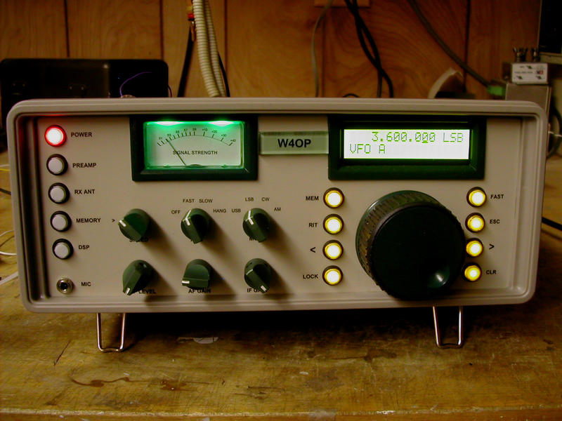
Eric Guth 4Z1UG interviewed Homebrew Hero Dale Parfitt W4OP on the QSO Today podcast. The interview is really great. Listen here:
https://www.qsotoday.com/podcasts/W4OP
Wow, libration fading. Who knew?
Dale has appeared in many SolderSmoke bolg posts and podcasts. He is definitely in the Homebrew Hero category.
Check out some of those blog posts here:
https://soldersmoke.blogspot.com/search?q=Parfitt
and here:
https://soldersmoke.blogspot.com/search/label/Parfitt–%20Dale
Thanks to Eric and Dale.
The Woz on Technology, Surplus Parts, Intercoms, and Ham Radio
Thanks to Dan Random for alerting us to this. During the first five minutes Woz talks about being an “electronics kid” and becoming a ham radio operator. For me also, wired intercoms were a precursor to ham radio.
More SolderSmoke blog posts on Steve Wozniak here:
https://soldersmoke.blogspot.com/search/label/Wozniak%20–%20Steve