Don’s drawing is so good, I just couldn’t resist posting it here. It is part of an article he did for the BITXHACKS blog describing how to add a Stockton bridge forward/reverse power meter circuit to your rig. Check it out:
http://bitxhacks.blogspot.com/2017/03/nd6ts-forward-and-reverse-power-meter.html
Month: March 2017
N7SUR’s Nice SSB Filter — Nail Polish Stuff Adds Soul to the New Machine
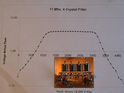
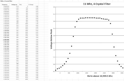
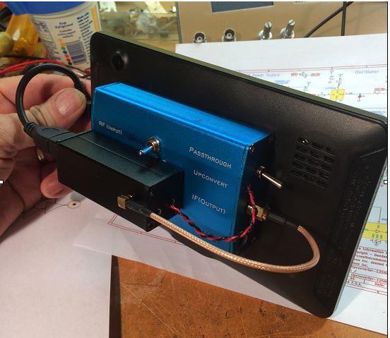
That’s a beautiful graph, don’t you think? In addition to the very pleasing results, I liked Bob’s methods: the “by hand” collection of the data points using an AD9850, a ‘scope and a notepad (see below); the filing down of ceramic disc caps; the use of nail polish hardener — all this adds a definite artisanal element to this project and puts more soul in the new machine.
Like Bob, I too kind of bailed out on the Q calculation when I was doing this. But as I recall there is a variation on the G3UUR method that yields this parameter too, right?
Bill:
I’m reluctant to share this with you because the results appear too
good. I’ve attached a graph showing my four crystal, 11Mhz
filter measurements. The graphed points are read values using my
AD9850 DDS VFO feeding to a TEK scope.
A TIA amp was used for input and output of the filter. My development software was the Steder-Hardcastle software as presented in November 2009, QEX.
I am now practiced in the black art of filing off the tops of disc
ceramic caps to “adjust” their values. This black art also involves
the mysterious qualities of Sally Hansen Nail Hardener.
Let me share my method for developing the filter.
I’ve built CW filters before but this was my first effort at SSB
bandwidth which is less forgiving.
The G3UUR oscillator method (see page 3.19 in EMRFD) is a simple and
effective filter design method. but it does not provide a measure for
crystal Q, a value which impacts filter insertion loss.
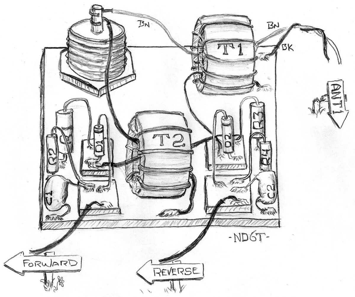
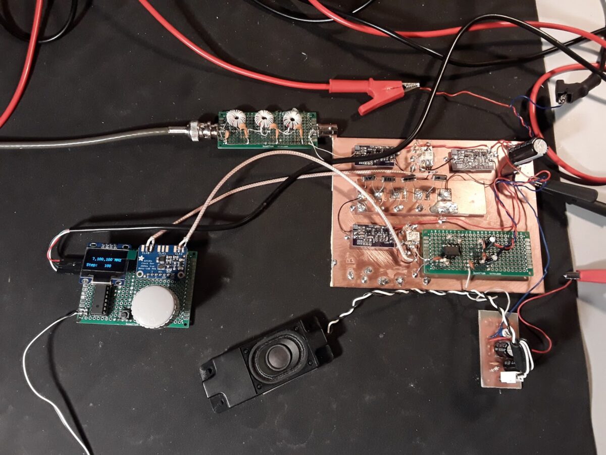
So I decided to choose crystals with proven pedigree. These were 11 Mhz crystals from Mouser, part number 20-HCA1100-S. A lot of ten costs $5. These were the crystals selected by Jim Kortge, K8IQY, for use in his 2N2/20 rig.
For software, I use the Dishal package that can be downloaded from the ARRL and other sources. This package was the basis for the
Steder-Hardcastle article in November 2009, QEX. The “Xtal” pull down
menu provides entries for an individual G3UUR oscillator.
Simply put, all critical filter input values are generated by reading
the change in crystal frequency as an additional capacitor is added
into the oscillator circuit.
I suggest starting with a 4 crystal filter. Only two capacitor values
were required for my filter. Five capacitors were required–two series
and three shunt.
Start by reading the “open switch” frequency for each crystal. Sort
the crystals into increasing frequency order and choose the four with
the most narrow frequency span.
Using the pull down menu measure the individual crystal measures for
Lm, Cm, and series frequency. Average these across the four crystals.
The Lm or Cm and series frequency are placed into the Dishal software
main menu. Also enter the average Cp which is the measured capacitance across the crystal leads.
Finish up the main menu entries by entering the number of crystals (4), and the desired bandwidth–generally 2.4 to 2.9 Khz. Finally enter the acceptable ripple, which is often 0.1db.
Let the software calculate the filter values. Expect some odd
capacitance values. By changing the filter bandwidth–say from 2.4 Khz to 2.35 Khz I can move one of the capacitance values to a standard value.
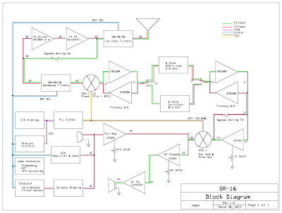
The software also displays the input and output impedance. If the
filter is centered between two TIA amps, this filter impedance must be
transformed to 50 ohms in the amps. This provides the transformer
winding ratios.
The Dishal software has always given me good results. But I haven’t
compared its results to Ladpac–especially GPLA.
Bob -N7SUR
Pete’s 60 Meter DifX
Oh man, run — don’t walk — to the N6QW blog and check out Pete’s amazing 60 meter DIFX transceiver. DifX is another N6QW contribution to the lexicon: it refers to a transceiver that has an architecture DifFERENT from that of our beloved BITXs. Pete means no disrespect to the BITX — he just sees the value in sometimes doing something different. I understand this completely — I myself am on my FIFTH BITX (three scratch-built and two modules) and definitely felt the need to do something different. (That’s why I built the OLED NE602 rig.)
Once again Pete Juliano shows himself to be a man ahead of his time: Anticipating FCC approval of a VFO tune-able segment in the band, Pete has made Channel 3 on his rig tunable with a rotary encoder. Hopefully, we will all soon need this. Pete is already there. FB OM.
My reaction to 60 meters has been very similar to Pete’s. We will talk about this on the next podcast (this Saturday).
Pete’s blog has a great description of the new rig, complete with a really nice video. Check it out:
http://n6qw.blogspot.com/2017/03/a-new-line-of-transceivers-difx_23.html
A Slovakian Al-Fresco Digi-Tia Homebrewed In France (and an improved AD9850 VFO)
Thanks for the podcast! My normal occupation is more computers and
software but your podcast got me motivated to melt some solder. So I
want to share a bit of what has been cooking on my bench.
I used to have a Yaesu FT-450 but sold it – I am living in a tiny rental
apartment in France without any place where to put a proper antenna so
it was only collecting dust. And where is the fun in operating a
factory-made rig, right?
So I have been working on this instead:
http://janoc.rd-h.com/archives/541
This “al fresco” rig is “half-DigiTIA”. Half because there is no
transmitter part (I don’t have a French license and I am too lazy to do
the paperwork and convert my Slovak one). The purple modules are TIAs,
as designed by Wes Hayward, using 3x 2n3904s, only built using SMD
components to keep them small and tidy.
VFO & BFO are Si5351 + ATMega328, with an OLED module and code adapted
from Pete N6QW. It uses 11.997450 MHz IF because that’s where most of my
12MHz crystals actually matched.
The 40m bandpass filter is taken verbatim from the BitX 40 design – I
have only changed the coils to use toroids instead.
For audio I have used LM386 with a NE5532 opamp as a low noise preamp
because the audio was a bit low. The TIAs don’t have a lot of gain and I
have only an indoor magnetic loop for antenna so had to compensate for it.
I have another, a bit older project that became quite popular – firmware
for the AD9850 DDS VFOs using an Arduino and a character LCD. It is a
much improved replacement for the one from Richard, AD7C.
http://janoc.rd-h.com/archives/502
Perhaps it could be useful to someone.
Keep up the good work and 73!
Jan OM2ATC (at the moment “in exile” in France)
An Si5351 Ham Sandwich from China (with video)
I must say, that nice little sandwich seems to be crying out for an organic slice of OLED…. How about it Adam?
About BD6CR/4
Adam Rong (Chinese name: Rong Xinhua), BD6CR/4 was first licensed in 1996 while in university in Hefei, Anhui province and now holds Class 2 Chinese amateur radio license (FCC Amateur General license equivalent). After graduation from university, he moved to Shanghai and call sign changed to BD6CR/4 in July 2003. Adam is now living in Pudong new district with his XYL and their son.
Adam holds a Master of Engineering degree in computer architecture and is an Engineering Program Manager in computer hardware industry. In spare time, Adam has written a lot about ham radio for magazines and papers, mainly about QRP, homebrew projects, APRS (Automatic Packet / Position Reporting System) and ham radio software applications. Adam has also translated two ARRL’s books into Chinese for Post and Telecom Press in China, including part of the ARRL Handbook and ARRL’s Low Power Communication: The Art and Science of QRP by Rich Arland, K7SZ.
You can contact Adam by email, or track Adam’s real time position on Google map by clicking this link.
N8NM’s SR-16 Hallicrafters Tribute RIg
DARK SIDE TO THE MAX: WA7HRG’s Android Tablet SDR (with a question)
Jim’s experience with the Android tablet SDR was very similar to mine. But he used a “Ham It Up” up converter ahead of the RTL-SDR while I used an RTL-SDR modified for direct sampling of HF. I built a pre-amp/pre-selector stage for mine. On my Android Tablet (50 bucks via Amazon) I found the touch screen to be kind of clunky — it was hard to get the receive passband lined up with the incoming signal. The touch screen was not nearly as smooth as the one on my IPhone. A Bluetooth mouse solved that problem.
Like Jim, I am using SDRtouch from the GooglePlay. I’ll have to follow his lead and try Droid RTTY and PSK.
My reaction to the completed project was also similar to Jim’s: He writes that this is, “The first and last of my SDR adventures. This is just not the same as scratch building!” Indeed, it is not. But still, for very little money you end up with a pretty impressive receive capability, and you get some valuable insight into an intriguing method of receiving radio signals. And you don’t have to mess with Linux!
I have a question for the SDR gurus: With direct sampling, we are just running an ADC at RF. So we no longer need an I-Q front end to take care of the image problem we had when we were running soundcard-based SDRs, right? But I sometimes I hear that even with direct sampling systems, there is a digital generation of I and Q signals. Why would you need I and Q if you are just digitizing the incoming passband, multiplexing it, and sending it to the software?
Hi Guys
OK, so I am a little (A LOT) behind you guys in my bench work. Several unfinished projects are waiting in the wings. But I thought I would also dabble in Software Defines Radios. Thought I would go the Raspberry Pi route as Pete did. Then I woke up and sided with Bill. I don’t want to learn Linux!!
For about the same price as a Pi-3 and a 7” screen I bought one of Bills Android tablets and I found on eBay an estate sale that had a bag of NuElec parts. The RTL dongle, a Ham it Up vs. 3, and several cables, all unused. Last but not least I bought an Android ‘On the Go’ USB cable adapter.
I removed the LED and UV diode for the remote to drop the current some. Then tapped some power off the USB connector and ran it out to the Ham it Up. A few holes and some double sided carpet tape and ‘Bobs Your Uncle”. I added an enable switch to the up converter for the noise source but still waiting for the SMA connector to come in. Then I’ll see what that can do as a poor man’s spectrum analyzer for filter design.
I found several interesting apps on GooglePlay. Besides the SDRTouch program I downloaded Droid PSK and RTTY. Also the RFCorb client that allows you to connect to hundreds of remote stations around the world. That I may have to spend some time exploring but not really part of this build.
The Up Converter fired right up and after tuning around some I jumped to 14.070, the PSK hot spot. The tablet truly does multitask. I left SDRTouch running and opened Droid PSK. A waterfall full of signals jumped up and I was easily copying stations on the East coast and Canada.
All this running on the USB power from the tablet! How cool is that. After about 45 minutes or so the battery was about half. The only problem that I may have to address is that the tablet and/or the Ham it Up gets pretty warm and my carpet tape lets go and things fall apart. HA. Haven’t ran it long enough yet to see what else the heat might effect.
So that was fun and I will be playing with it some more. I have coffee on Mondays with some ham buddy’s. When I showed them the PopCorn radio they jibbed about it not being battery powered.
Well Monday is coming!! HA
Jim WA7HRG
FB IBEW HB DC CW de UAE: A65DC’s International Homebrew Rig
Good evening!
Homebrew Canoe (video) (beautiful)
I post this because it is nice to occasionally look up from our soldering irons and take a look at what other people are building. This video is really beautiful.
Channelized! BITX 60 with the Five Channels (with video)
Here’s an update on my BITX 60 project. The modified module is in the lower box. An Arduino Uno and an Si5351 (this one with unreleased smoke) is in the Heath QF-1 box on the top. I am using an Arduino sketch written by Don ND6T. It spits out the needed 17 MHz LO freq needed for each of the five 60 meter channels. You can scroll through the channels by just holding down the rotary switch interrupt button.
There is a move afoot to liberate from channelization about 15 kHz of the 60 meter band. When that happens, I’m ready to go — I’ll just reconnect the rotary encoder for the Si5351 and load some new code. I suspect that by the time that happens, Don will have modified his code so that the 15kHz “tunable” segment will be integrated into the current program and will appear as one of the options as you scroll through the choices.
For reasons that most readers will understand, I have resisted channelization for many years. But here I am, channelized on 60. It is not so bad. I’m having fun listening to a new band, using a modified BITX, an Arduino, a bit of Heathkit and code from a fellow ham.
BITX 60 (with three short videos)
Inspired by Don ND6T, I decided to put a BITX40 Module on the 60 Meter band. All you really have to do is modify the bandpass filter. Don showed us how to do this by simply adding three 100pf caps. I was going to order SMD caps, but this just didn’t seem right — I found three of the old “with wires” kind and easily soldered them into position. The bandpass shifted as Don had promised.
You also have to change the VFO freq. You need it to be in the 17.3 MHz range. Don has a nifty program for the Raduino that also works with the Si5351/Ardunio Uno combo that I use. It keeps you on the five channels currently authorized on 60. Unfortunately I managed to let the smoke out of yet another innocent Si5351 breakout board. Amazon and Lady Ada are sending me another one, but in the meantime I pressed into service an old AD9850 DDS. I had a little trouble getting the 17MHz signal through the BITX’s VFO 4 MHz VFO system, but I eventually figured it out. (More on this later.)
The receiver is working nicely. I like the relaxed 60 meter conversations.
For Pi Day (3.14) – Looking Back on 5 years of Raspberry Pi Tinkering
Not by me, thank God! No, the five years of Rasp Pi maso-tinkering were done by Thorin Klowsowski. His report appears here:
http://lifehacker.com/what-i-ve-learned-from-tinkering-with-the-raspberry-pi-1793236686
In the second and third paragraph, he confirmed all my suspicions:
The Raspberry Pi is far, far away from being as user friendly as a PC or Mac. That’s a feature, not a bug… Before hobbyists latched onto the Raspberry Pi, it was a computer for learning how to code targeted mainly at kids. Since then, the appeal has broadened, but it’s still impossible for a project to “just work” out of the box. You will have to tweak something, dig into the command line, or spend a few hours buried in an obscure internet forum to find solutions to problems that only you seem to be having. You will slam your head against the wall, yell a little, and throw your Raspberry Pi at least once for every project you attempt to make.
I told you so.
KC1FSZ’s Peppermint Bark BITX: Aeronautical Mobile for his FIRST QSO. TRGHS.
Bill and Pete:
- First real QSO of my life was with KE4TJB “air-born mobile” off Delaware. He is a commercial pilot flying for JetBlue and apparently has time to work QRP stations during flights?? I wonder who was flying the plane?
- Then I was scanning around this morning and caught K4HW making last calls for check-ins on a net running on 7242 out of North Carolina. I decided to give it a shot, having never joined an HF net and I was recognized! As the first round got going I realized I had joined a Jehovah’s Witnesses net. They were very friendly and the net control stopped to help my get my frequency calibrated before they continued with the scripture passage for the week.
- Later this morning I reached K3KLC in Maryland who had the high-end SDR rig with the waterfall/panadaptor/etc. Remembering comments that you guys have made about these types of folks on 40m, I was very concerned. But this guy turned out to be very helpful and sent me some screen shots showing what my signal looks like.
WA8WDQ Builds OZ1JHM’s Arduino CW Decoder (Video)
Bill, Pete:
I wanted to update you on my DC receiver progress. While I’m still operationally proficient in CW, many of my friends are not. So I thought it would be fun to add a CW decoder to my DC receiver.
http://skovholm.com/cwdecoder) for details on his design and a video demo.
The Hobbyist Guide to RTL-SDR
Lots of good info in this book. I especially like the descriptions of how the useful properties of the dongles were discovered by hobbyists.
https://www.surviveuk.com/wp-content/uploads/2016/07/The-Hobbyists-Guide-To-RTL-SDR-Carl-Laufer.pdf
WU2D’s Wonderful Video on Retro-QRP
(Link to video appears below.)
Stephen G7VFY sent me the link to Mike WU2D’s Retro-QRP video. In the last month spoken to Mike at least twice on 40 and 75 meter AM. Stephen was responding to a post I did about a 1958 18 milliwatt solid state QRP rig.
Mike’s video is really wonderful. I’ve never been into military surplus, but this video made me think I might want an ARC-5. The rig Mike builds and tests is very similar to our beloved Michigan Mighty Mite. His description of the build and the testing procedures he used will be of great interest to those who’ve built the MMM rigs. And he made some contacts. Finally, there is a cameo appearance by Paris Hilton. And she is holding a HOT transistor! Wow!
Mike has a real talent for making these kinds of videos. Thanks a lot Mike — see you on 40. And thanks Stephen (Stephen has sent us so much great stuff over the years, including a fantastic box of British valves.) Pete: See how nice it is to get back to QRP?
Here’s Mike’s YouTube Channel. I love the intro:
https://www.youtube.com/channel/UCN7RQv_qmzhzuJV1HhJ4OEA
Beyond Al Fresco: Boxed Up In Style with AB1YK’s Very Cool BITX Box
Mike AB1YK is doing some excellent work boxing up the BITX.
Check out his article on the Nashua Area Radio Club Blog:
http://n1fd.org/2017/02/28/my-ssb-bitx-40-build-from-vu2ese/
Here is a picture of Mike’s case:
These enclosures might become available for purchase soon…
SolderSmoke Podcast 194 – Approaching the Digital-Analog Singularity
SolderSmoke 194 is available (scroll down for link)
March 4, 2017
Pete: Recycling Old Boards
Working on Arduinos and advanced displays
RTL-SDR is fun. Built HB front end.
HDSDR under Windows is fun and easy.
Thought about Raspi3, 7 inch touch screen, Linux, software YUCK.
Followed advice of Ken G4IIB and got a 50 buck tablet with Google Play.
The value of doing something different.
Boxed up my NE602 OLED rig.
OLED noise and ACTIVE decoupling.
NE602 and MOSFET tips
OTD Obsessive Tinkering Disorder G6LBQ
“A Thing of Beauty”
Source of Tombstoning term: Don ND6T.
Ken G4IIB’s extremely smooth audio.
On AM on 75 and 40. Fun. Old Military Radio Net and “The Lonely Guy Net” on 75 Saturday morning.
Good old 17 meters. Open at mid-day
HB2HB on 40 with W0PWE.
Listening on 60
EMRFD Classic Edition available
New Posts to BITX HACKS
Gloves follow-up. Not a good idea.
VK3YE’s QRP by the Bay event and a new book!
Colin M1BUU achieves Mountaingoat status
Martin A65DC JoO MMM in the UAE
Tom NY2RF Editorial with mention of JoO!
Lots of Al Fresco rigs: W8LM BITX on a board, Brad WA8WDQ DC RX, KA4KXX Al Fresco OZ DSB
ON6UU DSB from Spain via Belguim
Hugh ZL1UEM SMALL Si5351 OLED
Cookie Tin rigs VK2EMU’s Biscuit Tin DC RX, WA7HRG’s Popcorn rig
VK4FFAB FB LTSPICE intro
Ken G4IIB’s BITX adventure (with VERY smooth audio. How smooth? We can’t say.)
VU2XE’s BITX with a CAD box
G0ETP’s shockingly beautiful SDR receiver
Alan W2AEW on the mend with broken ankle. His videos are a treasure trove of tribal knowledge.
Farhan’s NEW uBITX Multiband Transceiver (video)
It is, truly, a thing of beauty.
Farhan will be posting details on his web site soon.
Jim WA7HRG’s Beautiful Popcorn BITX
Popcorn Radio
The main chassis. Across the back left to right are power input, spk jack, mic/PTT jack, ant connector, and 5/20 watt switch. Far right is the PA heat sink. A 1x.5×4″ aluminum bar. It’s what I had… Lower right corner is the tune push button and if you look close in the upper left corner of the main board is a mini relay glued to the board near the bal modulator. That unbalances the modulator and provides a carrier for antenna tuning. Upper left of the box below the power connector is the USB Sound Card for the PC interface. And a couple extra input wires I ended up not using. Below that is the standard Nano and si5351.
Last but not least is the 2.2″ TFT. All functions power, mode, etc., are DC switched. I also use that as inputs to the Nano for display changes. I sense the 12 v relay voltages and through a voltage divider to input pins.
It’s back to my General Coverage Rec that I started but never finished.


